Overview
Open Blink (Max) is a low-cost TIRF microscopy with laser combiner providing high-power homogeneous illumination for single-molecule based super-resolution imaging. The control system is fully integrated in micro-manager 2.0 .
Open Blink is inspired greatly by K2 TIRF at Ganzinger lab, the LaserEngine at Ries lab, and an flat-field illumination implementation. We also thank the Open Life Science program for helping with the documentation, and Open Hardware Funding at TU Delft for sponsoring parts of the project.
Schematic
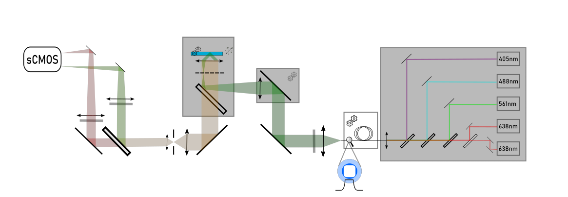
Laser Box
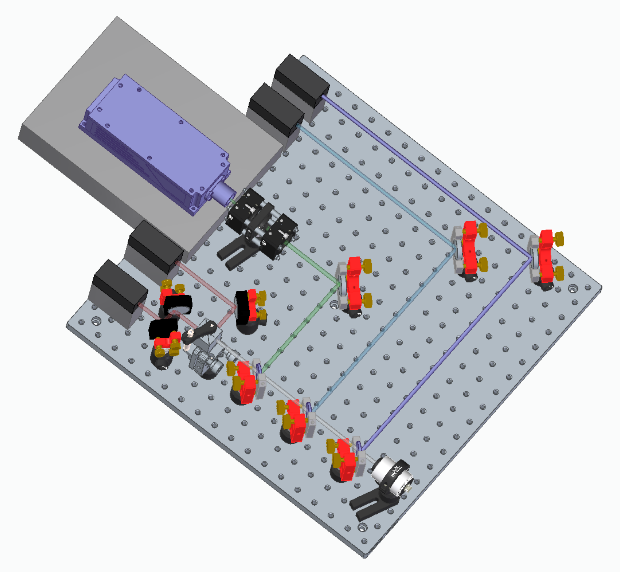
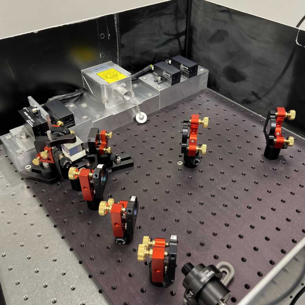
The laser box is contained within a 450*450 mm breadboard (MB4545/M) with enclosure. All lasers are raised up to 70(?) mm height with customised aluminum heat sink.
Model numbers are for Thorlabs unless specified otherwise.
| id | Title | Description | Image | Supplier, Model | Cost in € |
|---|---|---|---|---|---|
| 1 | Diode lasers 405 nm | 500 mW, with driver |  Diode laser and driver | Lasertack, LAB-405-500 | 687 |
| 2 | Diode lasers 488 nm | 2000 mW, with driver | Lasertack, LAB-488-1000 | 3310 | |
| 3 | Diode lasers 638 nm, 2x. One is oriented perpendicular to the other | 2x1000 mW, with drivers | Lasertack, LAB-638-1000 | 866 | |
| 4 | DPSS lasers 561 nm | 1000 mW, with analog modulation(0-5V) | CNI laser, MGL-FN-561 | 11150 | |
| 5 | Dichroics | 1" longpass dichroic mirros to combine the laser lines | Thorlabs, DMLP425/505/550/605 | 708 | |
| 6 | PBS | 1" polarisation beam spliter, mounted by KM100PM/M and PM4/M, in order to combine two 638 nm lasers | 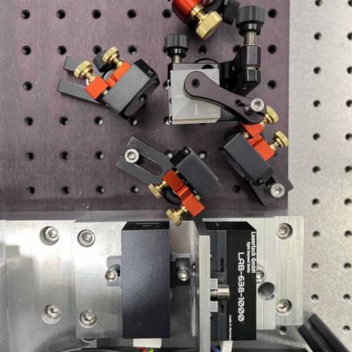 PBS | Thorlabs, PBS251 | 315 |
| 7 | Fiber launcher | A 1/2" 19mm ach. doublet (AC127-019-A) to focus the combined beam into the fiber. Mounted in 1" tubale lens tube (SM05V10, SM1A6, SM1M15, SM1TC), FC/PC adaptor(SM1FC) | 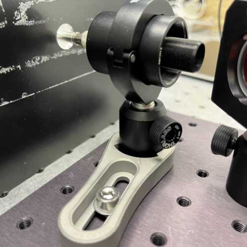 Fiber launcher | Thorlabs | 220 |
| 8 | Multimode fiber | 70*70 um square profiled MM optical fiber, NA=0.22 | Ceram Optec, Customized | 350 | |
| 9 | Vibrational motor | 9000 RPM vibrational motors that are taped onto the optical fiber to break down the speckles in the output beam profile | 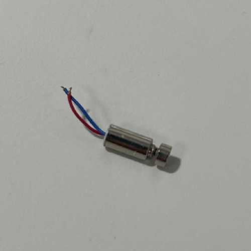 Vibrational motor  Vibrational motor mounting | Hackerstore.nl | 4 |
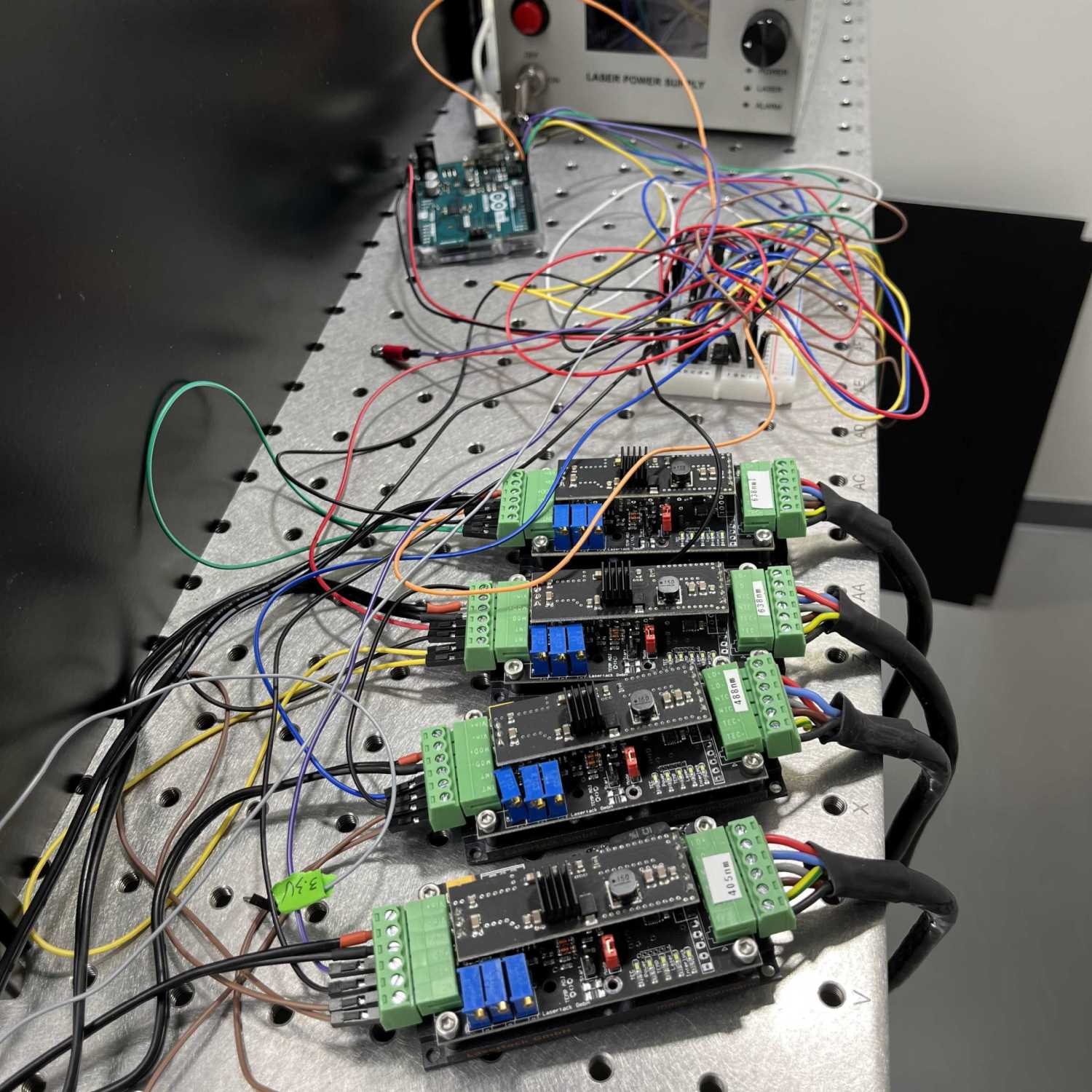
Laser box control
Excitation
| id | Title | Description | Image | Supplier, Model | Cost in € |
|---|---|---|---|---|---|
| 1 | Fiber adaptor | Couple out the beam at the output of the optical fiber mounted on cage plate (CP33/M) | Thorlabs, SM1FC | 30 | |
| 2 | Laser collimator | A 30 mm achromatic doublet to collimate the beam at the output of the optical fiber. Mounted in 1" cage after the fiber adaptor | 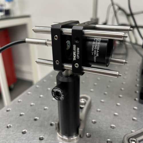 Laser collimator | Thorlabs, AC254-030-A | 85 |
| 3 | Laser cleanup filter | Filter out the autofluorescence from the MMF | Chroma, ZET 405/488/561/640xv2 | 575 | |
| 4 | TIRF stage | 1D motorised stage scanning the laser beam across the back focal plane(BFP) of the objective | 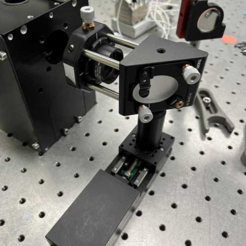 TIRF stage assembly | Thorlabs, KMTS25E/M | 1500 |
| 5 | TIRF lens | 150 mm achromatic doublets to focus the beam onto the BFP of the objective, mounted on CXY1A | Edmund Optics, 147-643 | 283 | |
| 6 | Elliptical mirror | Mounted on KCB1E/M and assembled with the TIRF lens on the TIRF stage | Thorlabs, BBE1-E02 | 70 | |
Microscope Body
| id | Title | Description | Image | Supplier, Model | Cost in € |
|---|---|---|---|---|---|
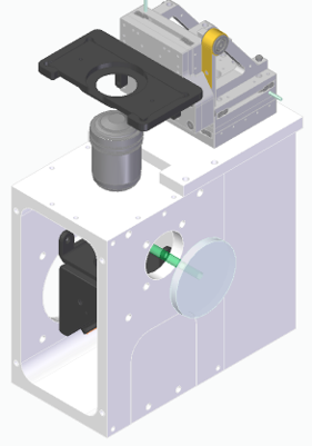
| 1 | Modified MiCube | Adapted from MiCube. Reduced in size to accommodate 150 mm focusing lens | 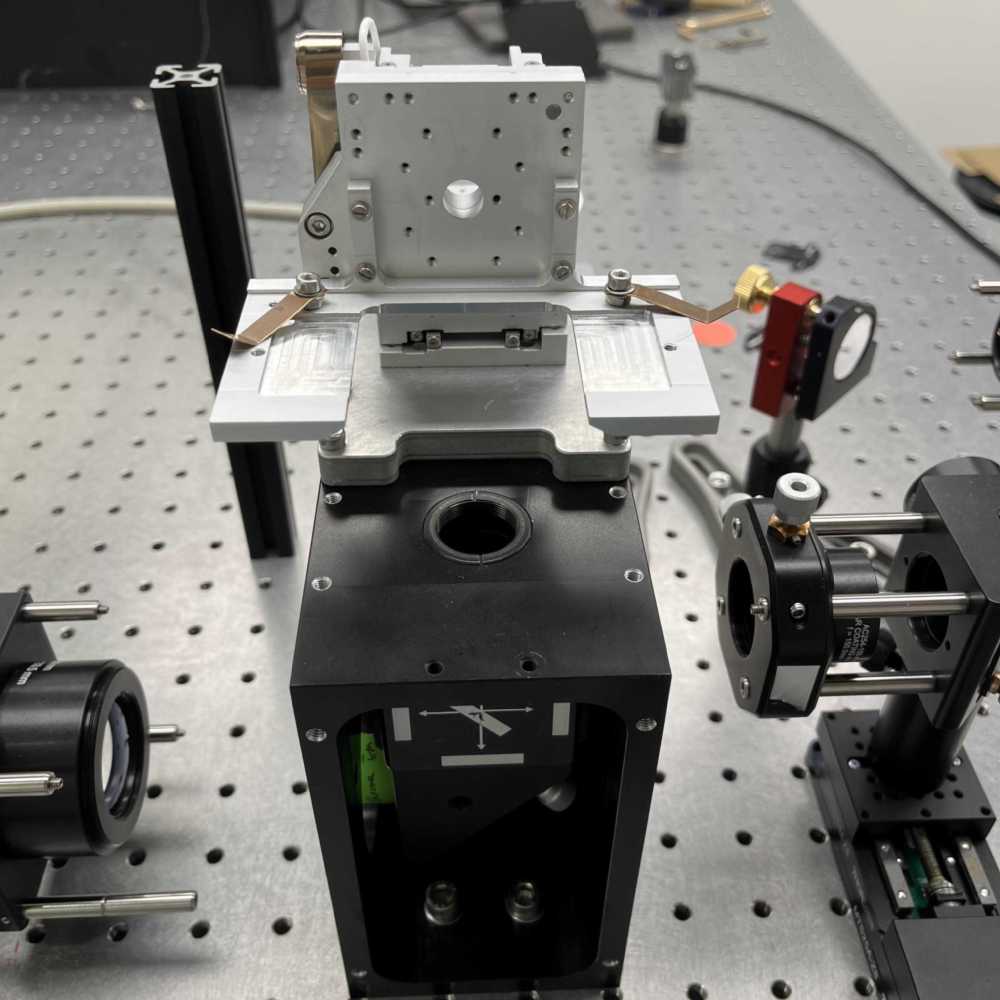 Micube | in-house CNC milled | 1700 |
| 2 | XYZ stage | Nano precision sample stage | Smaract, CLS5252 | 14000 | |
| 3 | Objective | Oil immersion objective, NA = 1,5. Mounted on the micube with M27 to RMS adaptor (RMSA3) | Olympus, UPLAPO60XOHR | 12400 | |
| 4 | Quad-band dichroic | Dichroic mirror under the objective, mounted on DFM1/M and fixed on the micube with screws on the back | Chroma, zt405/488/561/640rpc | 575 | |
| 5 | Elliptical mirror | Mounted under the dichroic mirror with KCB1E/M and C4W-CC | 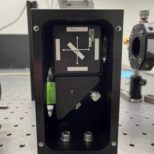 QUad-band dichroic and mirror mounted inside of Micube | THorlabs, BBE1-E02 | 65 |
| 6 | Sample holder | Home-made slide holder, mounted onto the stage | In-house CNC milled | \ | |
Detection
We adapt the detection scheme in K2 TIRF at Ganzinger lab for our dual channel detection.
| id | Title | Description | Image | Supplier, Model | Cost in € |
|---|---|---|---|---|---|
| 1 | Tube lens | 180 mm tube lens compatible with Olympus objectives | Thorlabs, TTL180-A | 686 | |
| 2 | Notch filter | Filter out the excitation laser beam | Chroma, ZET405/488/561/640m-TRFv2 | 1000 | |
| 3 | Slit | Semi rectangular slit adjustable from two directions, cropping the image to fit in a single channel on camera. Alternative could be Owis SP60 | 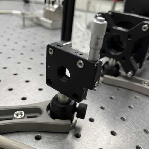 Slit | Recycled from MadCityLab RM21 | |
| 4 | 4f lenses | Three 300 mm achromatic doublet mounted on LMR1/M | 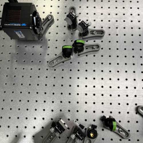 Two channle 4F system | Qioptiq, G32 2336 322 | 300 |
| 5 | Dichroic mirror | Long-pass dichroic splits image into red and green channels, glued on compact KMS/M with picodent Twinsil | Chroma, ZT640rdc-UF3 | 450 | |
| 6 | Square mirror | Reflects the green channel with maxium surface, mounted on compact KMS/M | Thorlabs, BBSQ1-E02 | 74 | |
| 7 | Emission filters | Band-pass filters in the red and green channels respectively | AHF, ET685/70, ET595/50 | 650 | |
| 8 | Camera | sCMOS camera | Teledyne Prime BSI Express | 10800 | |
× 
This is a sample text to enlarge the div window