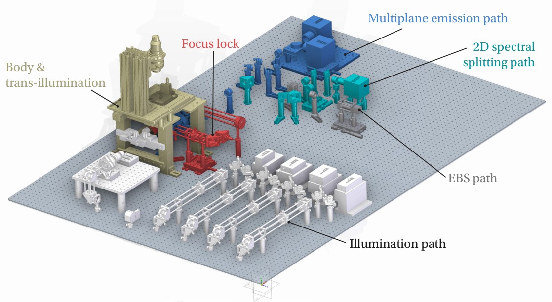
PRISM is the widefield multiplane, multicolour super-resolution platform of the Grussmayer Lab at TU Delft. It follows the foundational study on correlative super-resolution fluorescence and multiplane quantitative phase microscopy, and is built as a workhorse instrument: one sample, one illumination arm, and several exchangeable detection arms that can be addressed without realigning the microscope.
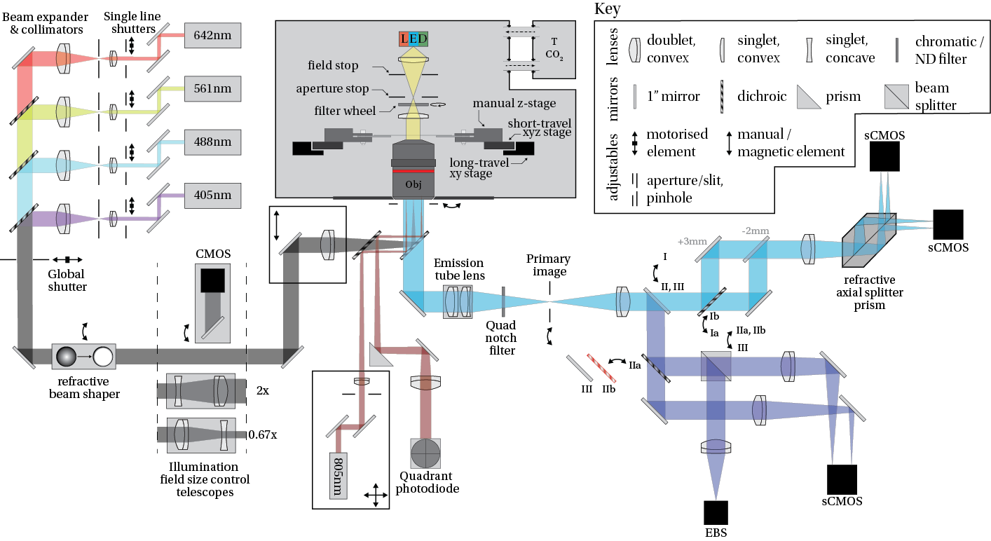
On the excitation side four continuous-wave lasers covering the standard wavelengths for biological applications (405 nm, 488 nm, 561 nm, 642 nm) plus an infrared diode laser (830 nm) for the focus lock are mounted. Three illumination geometries are available: (I) a dynamically adjustable dichroic-based Epi-TIRF path with refractive beam shaping, (II) a micro-mirror based objective TIRF path, and (III) a manually positionable LED-based Koehler transillumination for brightfield and quantitative phase imaging. Emission is directed into one of three detection arms: (1) an image-splitting prism producing eight simultaneous focal planes on two sCMOS cameras, (2) a 2D spectral splitter for robust simultaneous multicolour imaging, and (3) an event-based sensor (EBS) arm for high-speed, sparse-signal imaging.
The implementation used in the lab is based on an RM21 body (Mad City Labs, US), which is commercially licensed and can therefore not be shown in CAD; reduced representations of the body are used in the figures below. The PRISM detection concept is not restricted to this body and can be implemented in essentially any widefield, camera-based configuration. A summary of the chromatic properties of the current configuration is available at FPbase. Devices are controlled through micro-manager 2, with acquisitions either set manually, scripted in beanshell, or interfaced through pycro-manager.
System overview
| Property | Specification |
|---|---|
| Excitation | 405 nm / 488 nm / 561 nm / 642 nm CW, up to 2 W per line; refractive beam shaping (flat-top) on the Epi-TIRF path |
| Illumination modes | Epi, dichroic-based Epi-TIRF (translatable TIRF module), micro-mirror objective TIRF, LED Koehler transillumination |
| Objectives | 60× silicone/water immersion (UPLSAPO60XS/W) and 60× oil immersion high-NA (UPLAPO60XOHR) |
| Sampling | 108 nm per pixel in the sample plane (200 mm tube lens, 6.5 µm sensor pitch), verified on both camera models against a calibration grid |
| Multiplane detection | 8 simultaneous focal planes, distributed 4 + 4 over two Kinetix sCMOS cameras |
| Spectral detection | 2D splitter for up to four colours on a single BSI Express sCMOS; optional two-colour row splitting in the multiplane arm |
| Stabilisation | 830 nm reflection focus lock (Mad City Labs TIRF Lock, quadrant photodiode) on the micro-mirror path, closed loop onto the piezo z-stage |
| Environment | Custom cage incubator with Okolab bold-line temperature and CO2 control (37 °C, 5 % CO2) |
| Control | micro-manager 2 + pycro-manager, Arduino-based shutter and line switching, Mad City Labs MicroDrive XY and NanoDrive Z, PVCAM cameras |
Main body
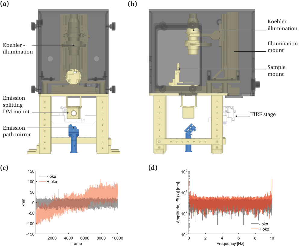
The objective, the sample stages (also Mad City Labs) and the dichroic filter cube outlined here are mounted in the RM21 body. The body carries the Koehler transillumination on 95 mm rails above the sample, the sample and objective positioners, and the emission splitting dichroic mount that feeds the detection breadboard.
| id | Title | Description | Image | Notes | Costs/Supplier |
|---|---|---|---|---|---|
| 1 | RM21 Advanced | Precision aligned Epi-flourescence microscope platform | 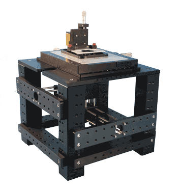 RM21 advanced | link | Costs/Mad City Labs |
| 2 | MicroStage Series | Large (micron - cm) displacement, precision, stepper motor driven, micropositioning system for inverted optical microscopes | 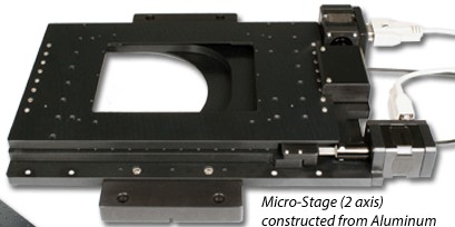 Micro-stage | Addressed as MicroDrive XY Stage and MicroDrive Z Stage in micro-manager | Costs/Mad City Labs |
| 3 | NanoStage Series | Closed-loop piezo z-positioner used for z-stacks, multiplane calibration and as the actuator of the focus lock | Addressed as MCL NanoDrive Z Stage in micro-manager | Costs/Mad City Labs | |
| 4 | TIRF-module | Precision aligned linearly translatable mirror-lens configuration to control the angle of illumination and the focusing of the excitation beam onto the back focal plane of the objective lens. | 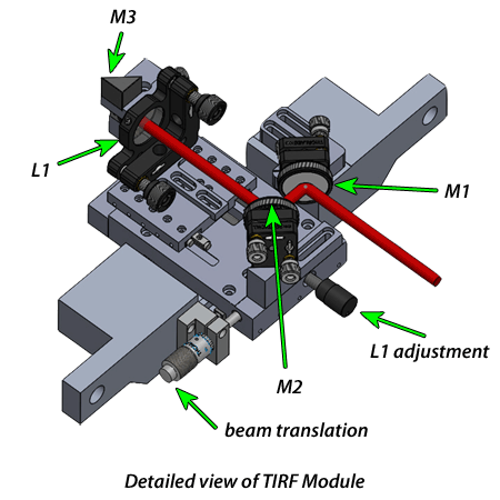 TIRF-module | Continuous transition between epi, HILO and TIRF illumination | Mad City Labs |
| 5 | Micro-mirror | Two broadband micro-mirrors positioned at the back aperture of the objective lens. | 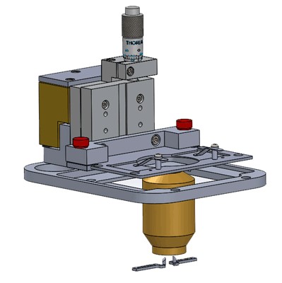 Broadband micro-mirrors for TIRF imaging and TIRF-lock simultaneous to dichroic based Epi-TIRF | Broadband micro-mirrors for TIRF imaging and TIRF-lock simultaneous to dichroic based Epi-TIRF | Mad City Labs |
| 6 | Notch-filter | F40-072 Quad-Notch 400-410/488/561/631-640, mounted in a cage plate. | Placed in the emission path behind the tube lens, blocking all four excitation lines ahead of the splitting optics | AHF, Semrock/ 1100€ | |
| 7 | Objective(s) | 60X Super-Apochromate Olympus immersion medium (silicone oil, water) UPLSAPO-S/UPLSAPO-W and oil immersion UPLAPO60XOHR |  60x high NA immersion objectives | Silicone and water immersion for live-cell volumes, oil immersion for single-molecule work close to the coverslip | Olympus/ |
| 8 | Dichroic mirror | ZT405/488/561/640rpcv2-UF2 mounted in magnetic Kinematic Fluorescence Filter Cube DFM1/M | 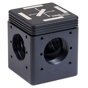 TL dichroic mirror | Ultraflat version to preserve the wavefront across the full field | Chroma/600€ Thorlabs/350€ |
| 9 | Tube lens | Thorlabs TTL200-A f = 200 mm tube lens | With the 60× objectives this yields 108 nm sampling on 6.5 µm pixels. Mounting is detailed in the detection front end table | Thorlabs | |
| 10 | Environmental chamber | Cage incubator enclosure covering the stage and trans-illuminatsion, interfacing with the 75mm rails. Edges are sealed with tape, space inbetween breadbord and body is sealed with a folded rubber sheet. Tubing interfaces are designed according to oko-lab specifications. Two doors back and front-side are fixed to the body with M6 threads and knobs. | 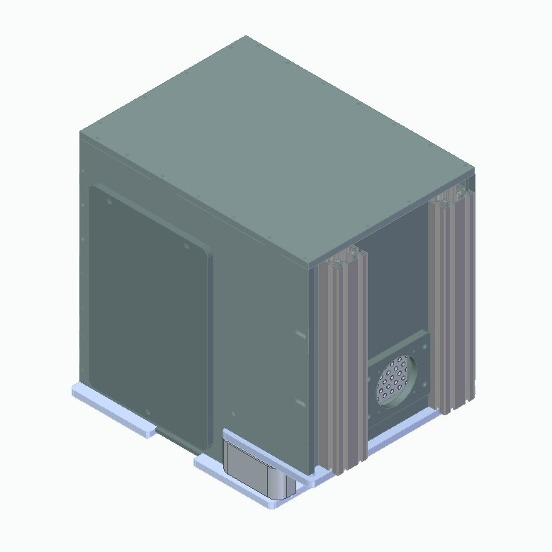 Environmental chamber designed in SolidEdge | Design and assembly are documented on the live-cell incubator page | self made |
| 11 | Environmental control | Oko-lab bold line temperature and CO2 control | Setpoints of 37 °C and 5 % CO2 are reached and held within about an hour after closing the enclosure | Okolabs/ | |
| 12 | Koehler-illumination | OLY-TRANS-ILLUM transillumination kit based upon Olympus IX2-LWUCD condenser suspended on a XT95SD-250 95 mm one-sided rail with XT95RC4/M rail carriers, fixed to XE50L1/M 50 mm square construction rails | 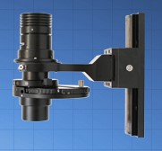 Koehler illumination based on Olympus IX2-LWUCD condenser | Construction rails are cut to 300mm height and fixed to the breadboard above the stage with right angle brackets | ASI/ Thorlabs/ |
| 13 | Trans-illumination stops and filter wheel | Field stop, two filter wheels. One in the LED transillumination arm above the condenser, used to set Koehler conditions and to insert neutral density or chromatic filters for brightfield and quantitative phase imaging. The other an emission path filter wheel which has been removed by now due to the split detection paths, but can be implemented per chromatic path for computational control. | Emission path filter wheel based on the Ries lab 3D printed design | self made | |
| 14 | Sample positioning | Long-travel xy stage, short-travel xyz stage and a manual z-stage | Long-travel xy = MicroStage, short-travel xyz = NanoStage (rows 2 and 3); manual axial sample positioner | Mad City Labs/ | |
| 15 | Optical table | Thorlabs T1530D Nexus optical table, 1.5 m × 3 m × 310 mm, M6 mounting holes | Carries body, illumination and detection breadboards | Thorlabs | |
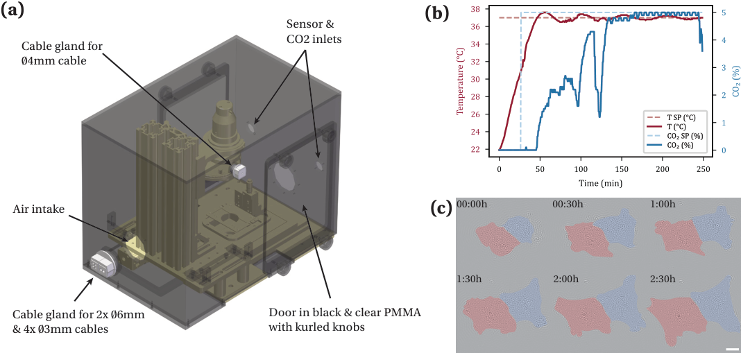
The enclosure is a workshop-manufactured PMMA box (drawing set GELD010084) that seals against the breadboard and the 75 mm construction rails. Its bill of materials is reproduced below; the individual part drawings and the STEP geometry are linked under design files.
| id | Part | Description | Qty | Material | Supplier / order number |
|---|---|---|---|---|---|
| 1 | GELD010084-M201–M204 | Front, back, left and right wall | 1 each | PMMA black (Plexiglas) | workshop manufactured |
| 2 | GELD010084-M205–M207, M211 | Bottom cover, top cover, bottom cover sides and close-off | 1–2 each | PMMA black (Plexiglas) | workshop manufactured |
| 3 | GELD010084-M208 | Side covers / doors | 2 | PMMA clear + black | workshop manufactured |
| 4 | GELD010084-M209, M217, M218 | Side cover gaskets and rubber sealing plates between breadboard and body | 2 / 2 / 1 | NBR 70 SUPERBA sheet | ERIKS 10017236 |
| 5 | GELD010084-K201, K202, K204, K206 | Self-adhesive cell rubber sealing strips along the enclosure edges | 1–2 each | CR FEST cell rubber, black | ERIKS 10000000 |
| 6 | GELD010084-K207 | Icotek KVT 50-2 cable entry frame — main pass-through for stage, camera and sensor cabling | 1 | Polycarbonate | RS 2844658 |
| 7 | GELD010084-K208–K211 | Icotek QVT 20, QT3, KT 4|3 and KT 2|6 cable grommets for the Ø3 mm, Ø4 mm and Ø6 mm cables | 1 each | Polycarbonate / elastomer | RS 2836507, 2836500, 2844652, 2837600 |
| 8 | GELD010084-K213 | ITEM angle bracket 60×40×20, fixing the enclosure to the construction rails | 4 | Zinc plated steel | ITEM 0047461 |
| 9 | GELD010084-K214 | Knurled torque knob M5 × 20, 22 mm diameter, for the doors | 8 | — | RS 702-7541 |
| 10 | GELD010084-K215 | Connector 2711-nc13 for the sensor and CO2 feedthroughs | 2 | — | |
| 11 | GELD010084-M219 | Adjusting plate | 2 | Aluminium | workshop manufactured |
| 12 | GELD010084-S202 | Two-step platform | 1 | Various | workshop manufactured |
| 13 | DIN 912 | Socket head cap screws M3×10 (10×), M5×16 (4×), M6×12 (8×) | 22 | Stainless A2-70 | Fabory 51050.030.010 / .050.016 / .060.012 |
Excitation
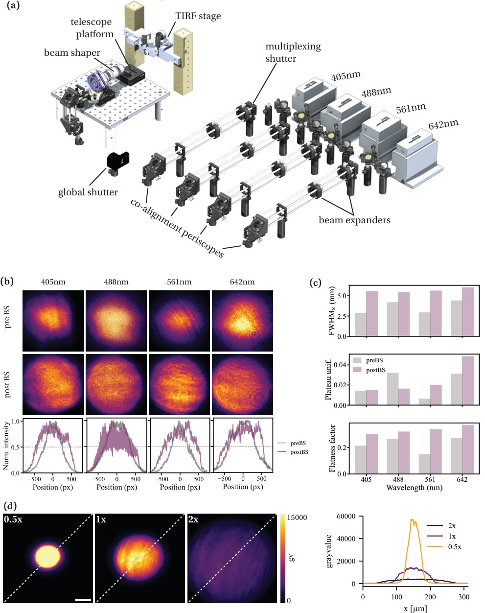
Four visible excitation lasers with comparably high power levels (>500 mW for the imaging lines) are deployed. The lines are individually expanded, co-aligned on dichroic mirrors and split into two illumination paths by a flip mirror. The main path passes the refractive beam shaper and enters the TIRF module for dichroic-based Epi-TIRF; the secondary path is routed via height-separated periscopes to the micro-mirror TIRF configuration. All optomechanics are mounted on 12 mm optical posts and post holders (Thorlabs) at a beam height of 126 mm.
Beam shaping matters for quantitative single-molecule work: the Gaussian profile delivered by the expanders is converted into a flat top, which widens the usable field, equalises the switching rate across it and removes the intensity gradient that otherwise biases localisation statistics. Behind the shaper two switchable telescopes (2× and 0.67×) set the diameter of the illuminated field, trading field size against intensity, and a flip mirror sends the beam to a monitoring camera for the profile measurements shown below.
| id | Title | Description | Image | Notes | Costs/Supplier |
|---|---|---|---|---|---|
| 1 | Toptica IBEAM-SMART-405-S-LP | Ultra Compact Diode Laser, 405 nm, 100 mW | Mostly used for reactivation in STORM and photoactivation in PALM, not easily alignable with Tetraspeck beads. | Toptica / ~2700€ | |
| 2 | Coherent Sapphire LPX-488nm | CW laser, 488 nm, 500 mW | Pmin: 50mW, needs OD filters for conventional imaging | Coherent / ~15000€ | |
| 3 | LaserQuantum gem 561nm | DPSS laser, 561nm, 1W; with smd2 controller | Serial control through micro-manager | LaserQuantum / ~13000€ | |
| 4 | MBP communications laser, 642nm | TEM00, Modell 2RU-VFL-P-2000-642-B1R, 642nm, 2W | Main STORM excitation line, used at several kW cm-2 at the sample for off-switching | MBP communications / ~21000€ | |
| 5 | Beam expanders | Based on 30mm cage system from Thorlabs (US) with CP33/M cage plates, 30mm rods, CXY1A xy-translating & SPT1CT/M slip plate lens mounts & 1" achromatic AR coated VIS doublet lenses. | Lens pairs chosen depending on the input laser diameter to adjust laser Ø (1/e2) to 6mm. Fine adjusted with individual circular apertures downstream. Collimation is verified with a shear plate interferometer. | Thorlabs/~600€ per expander | |
| 6 | Kinematic mirror mounts | KM100 1" mirror mounts with Visible Laser Quality Mirror | Thorlabs/110€ | ||
| 7 | Dichroic mirrors | KCB1/M mounts with broadband dielectric mirror (BB1-E02) and longpass dichroics LM01-613-25, LM01-503-25, LM01-427-25 | Co-alignment of the four lines onto a common axis ahead of the beam shaper | Thorlabs/600€ Semrock/250€ p.p. | |
| 8 | Beam shutter | SH1/M with KSC101 solenoid shutter controller | Camera triggered (dual BNC>SMA via solenoid controller) per detection path; a global shutter plus per-line multiplexing shutters allow sequential multicolour acquisition | Thorlabs/1500€ | |
| 9 | Flip mirror | ZT 750 LPXRxt-U2 in kinematic mirror mount KM100CP/M on a FM90 flip mirror mount. | Selects between the Epi-TIRF and micro-mirror TIRF paths; the longpass edge lets the 830 nm focus-lock beam share the path | Thorlabs/200€ Chroma/250€ | |
| 10 | Beam homogenisation | piShaper (6_6 series) in a 4-Axis πShaper Mount M27 mounted on a BA2/M post base on top of 12mm posts. | Laser input requirements: Ø (1/e2) 6mm, lateral displacement ±0,1 mm; angular tilt ±0,1°. Robust alignment for all input lines not trivial. | AdlOptica/~5000€ | |
| 11 | Periscopes | Beam height adjustment tailored to RM21 input heights of Epi-TIRF and micromirror path with KCB1C/M 90° kinematic mirror mounts, end plates and 30mm cage system. | The CAD assembly models these as KCB1EC/M right-angle kinematic mounts on ER cage rods | Thorlabs/~350€ per unit | |
| 12 | Single-line shutters | One mechanical shutter per laser line ahead of the co-alignment dichroics, for line multiplexing during sequential multicolour acquisition. SH05R/M shutters with SHB05 blades in SHCP025/M cage plates | Switched over the Arduino TTL hub (Arduino-Shutter / Arduino-Switch in micro-manager). Run indepdenetly of the global shutter SH1/M unit in row 8 | Thorlabs | |
| 13 | Illumination field size control telescopes | A bi-directional galilean type telescope (2× and 0.5×) behind the beam shaper that set the diameter of the illuminated field at the sample without changing the flat-top profile. | Corresponds to the 0.5× / 1× / 2× settings characterised in the illumination figure. Uses a f = 50mm convex doublet (AC254-050-A) and a f = −25mm bi-concave singlet (LD2297-A) on kinematic translation mounts in a ø1” cageplate with 100mm cage rods. | Thorlabs | |
| 14 | Beam monitoring camera | IDS GigE uEye CP Rev. 2 (housed) CMOS camera with 1"-32 UN C-mount thread, RJ45 GigE interface and 8-pin I/O, mounted in the beam path of the removable mirror on the magnatic base behind the beam shaper to record the beam profiles for the flatness and plateau uniformity measurements | Addressed in micro-manager as IDSCam through the IDS peak device adapter; also used for the infinity alignment target tooling | IDS | |
| 15 | Relay and collimation lenses | Mounted achromatic doublets in the expander and relay stages, e.g. AC254-200-AB-ML (Ø1", f = 200 mm) and MAP103050-A matched achromatic pairs | Held in LMR1/M, LM1XY/M or CXY1A mounts depending on the position in the path | Thorlabs | |
| 16 | Irises and beam stops | SM1D12D SM1 iris diaphragms used to trim the expanded beams and as alignment references along each line | One per line downstream of the expander, as described in row 5 | Thorlabs | |
| 17 | Optomechanics | TR20V/TR30V/TR50V/TR75V Ø12 mm posts in PH20/PH50/PH100/M post holders on BA1S/M and BA2/M bases, CF125C/M clamping forks, KB25/M, KB75/M and KBM1/M kinematic magnetic bases, ER-series cage rods and LCP33/M, LCP34/M, LCP4S, CP36 cage plates | Thorlabs | ||
Detection
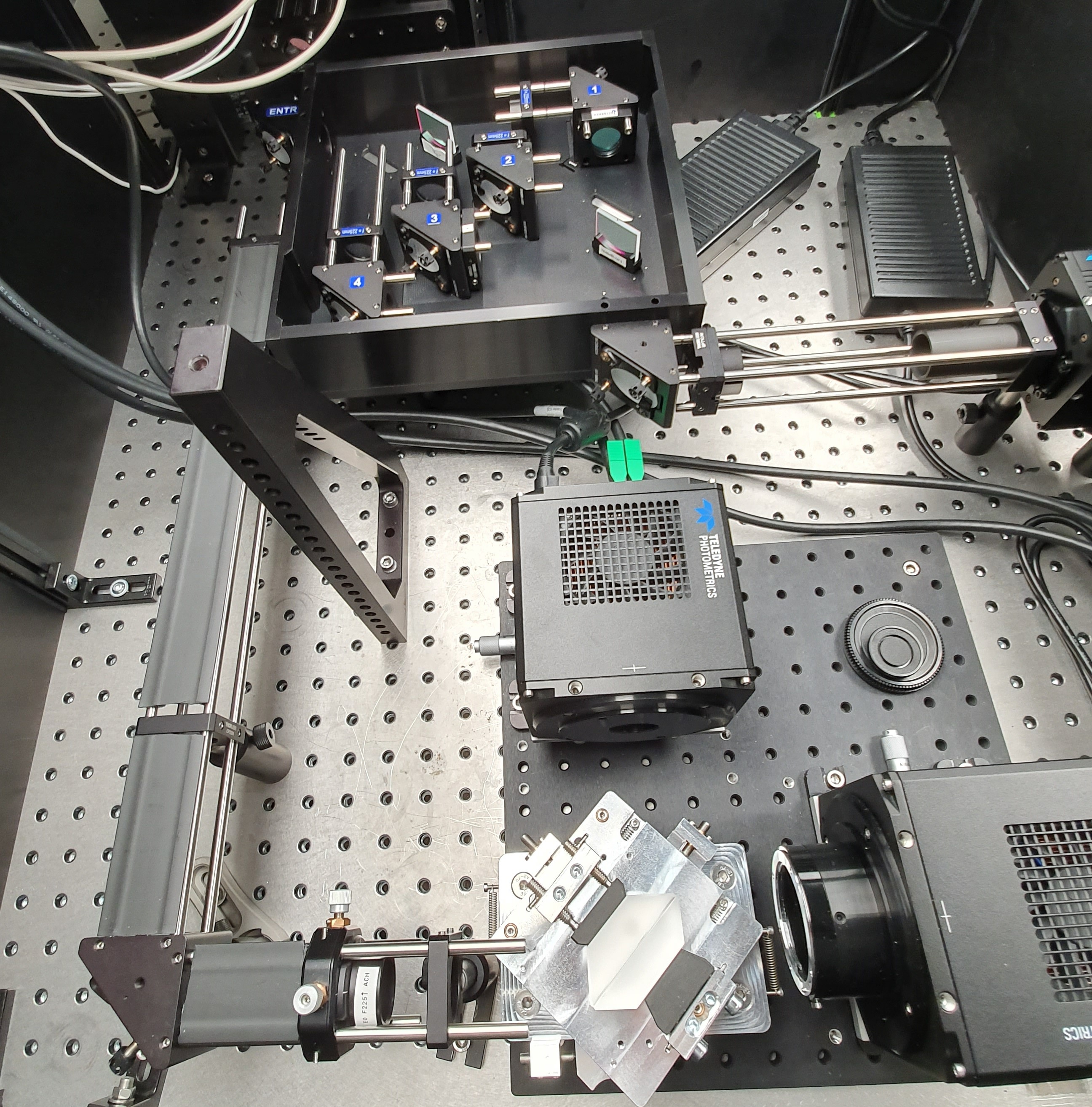
The emission is collected by the objective, passes the tube lens and a shared square field stop, and is then directed by a flip mirror (Mch) into one of the detection arms. Each arm is built as a 4f relay so that the field stop is imaged onto the sensor and the splitting element sits close to a pupil plane.
| id | Title | Description | Image | Notes | Costs/Supplier |
|---|---|---|---|---|---|
| 1 | Emission tube lens | Thorlabs TTL200-A f = 200 mm tube lens in a CXY2A 60 mm cage XY translating mount, carried by LCP33/M and LCP34/M cage plates on ER cage rods and PH50/M post holders | Forms the primary image together with the objective; sets the 108 nm sampling | Thorlabs | |
| 2 | Quad notch filter | Quad-notch 400-410/488/561/631-640 emission filter in the collimated space behind the tube lens (see the body table, row 6) | Blocks the four excitation lines ahead of the splitting optics | AHF, Semrock/ 1100€ | |
| 3 | Field stop | SP 60 square aperture with four separately positionable edges, mounted on a BA1S/M base with a clamping pedestal at the primary image | 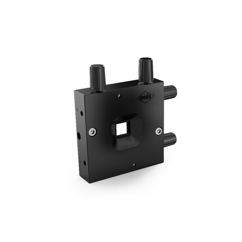 Square aperture with 4 separately positionable edges | max. 12 x 12 mm, shared between the detection arms; has to be set manually to the preset field of view of the selected arm | Owis/ 450€ |
| 4 | Path selection mirror Mch | Broadband dielectric mirror (BB1-E02) in a KMS/M kinematic mount on RS-series pillar posts, seated on a KBM1/M kinematic magnetic base | The magnetic base allows switching between the detection arms and returning to the aligned position without realignment | Thorlabs | |
| 5 | Detection breadboard | Thorlabs MB3030/M 300 × 300 mm aluminium breadboard carrying the splitter and the cameras, raised on RS-series pillar posts | Keeps the whole splitter arm as one transportable, pre-aligned unit | Thorlabs | |
| 6 | Light shielding | Enclosure separating the two detection arms and shielding the sensors from stray room light | Self made, based on blackout metal and cardboard sheets sliding into 25mm construction rails, modelled by workshop. Walls and illumination side cover made from anodized aluminium with small cutouts for cable management. Detection side top cover made from blackout cardboard (href="https://www.thorlabs.com/item/TB4">TB4) for simplified adjustments (needs to be cleaned for splinters after cutting). | self made | |
Multiplane splitter
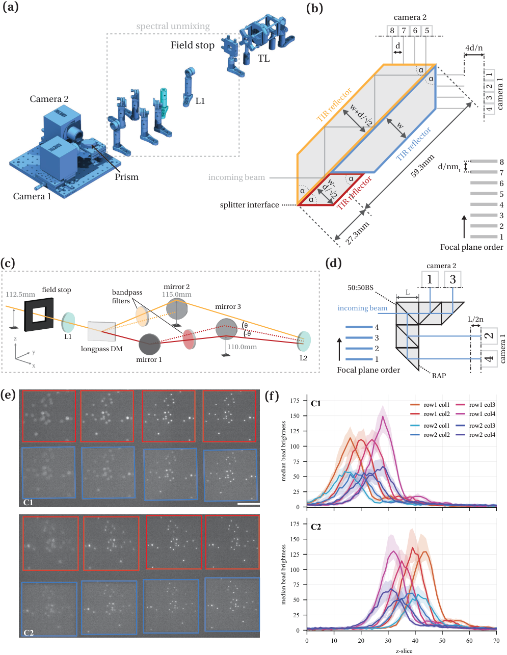
The multiplane arm images eight focal planes simultaneously. An image-splitting prism with three totally internally reflecting faces divides the beam into eight paths of successively increasing optical path length; four of these are relayed onto camera 1 and four onto camera 2, so that each sensor records a row of four laterally separated sub-images. The optical path increment d between neighbouring paths translates into an axial plane spacing of d/(n·mt) in sample space, set by the refractive index of the prism glass and the transverse magnification of the relay. The prism used here measures 59.3 mm × 27.3 mm.
The arm can be operated monochromatically, or with an optional spectral-unmixing insert that splits the field into two colour rows ahead of the prism: a longpass dichroic separates the emission, each arm is filtered by its own bandpass, and the two beams are recombined at slightly different angles (±θ) so that they land as two vertically offset rows on each camera. Combined with the eight planes this gives up to sixteen sub-images. An alternative, simpler four-plane arrangement based on a 50:50 beamsplitter and a right-angle prism (plane spacing L/2n) is shown in the same figure for setups that do not need eight planes.
Ahead of the prism a set of kinematic folding mirrors introduces small, adjustable path length offsets between the sub-beams (+3 mm and −2 mm in the current configuration), which shifts the plane spacing without exchanging the prism. Plane calibration is then performed on fluorescent beads: a z-stack through the sample yields the brightness profile of every sub-image, and the offsets between the profile maxima give the axial position of each plane as well as the inter-plane distances used in the reconstruction.
| id | Title | Description | Image | Notes | Costs/Supplier |
|---|---|---|---|---|---|
| 1 | Fourier lens Fm,R1 | #49-366-INK 25mm Dia. x 250mm FL, VIS-NIR, Inked, Achromatic Lens (400-1000nm) | Collimates the intermediate image relayed from the field stop | Edmund optics/ 120€ | |
| 2 | Fourier lens Fm,R2 | #49-365-INK 25mm Dia. x 225mm FL, VIS-NIR, Inked, Achromatic Lens (400-1000nm) | Sets the transverse magnification mt of the relay and with it the axial plane spacing | Edmund optics/ 120€ | |
| 3 | Beam deflection mirror | KCB1/M mount with broadband dielectric mirror (BB1-E02) | 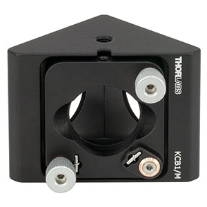 KCB1/M | Inserted due to spatial constraints | Thorlabs 300€ |
| 4 | Multiplane-splitter | Image splitting prism with three TIR reflectors, 59.3 mm × 27.3 mm, distributing eight optical paths over two cameras | 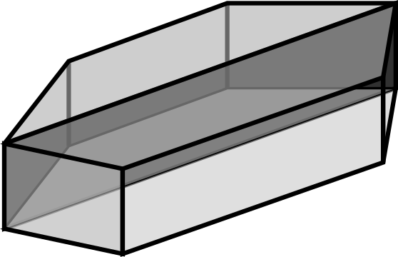 Image splitting prism, eight paths distributed over two cameras | Allows simultaneous detection of diffraction limited images at equally spaced axial planes with only minimal alignment of the overall optical setup. Assembly from off-the-shelf beamsplitters is documented on the prism fabrication page | Scoptonic Imaging technologies/10-20k€ |
| 5 | Multiplane-splitter-mount | Multi-plane prism aligner | 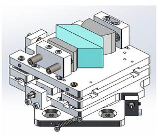 Multi-plane prism aligner, Scoptonic Imaging technologies | Multi-Axis stage: X, Y, Z, Pitch, Yaw and Roll adjustment | Scoptonic Imaging technologies |
| 6 | Spectral unmixing insert | Longpass dichroic, two bandpass filters and three folding mirrors placed at 112.5 mm / 115.0 mm / 110.0 mm that recombine two colour channels under ±θ | Optional; splits every plane into two vertically offset colour rows on the sensor | Thorlabs, Semrock/ | |
| 7 | 2x sCMOs cameras | Teledyne Photometrics KINETIX | 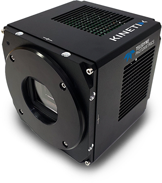 Teledyne Photometrics KINETIX | 3200 x 3200 pixel, air/water cooled, 83Hz full range full chip, high sensitivity sCMOS; addressed as a MultiCamera device through PVCAM | Teledyne Photometrics |
| 8 | Path length trim mirrors | Kinematic folding mirrors (labelled I, IIa,b, III in the schematic) that add the +3 mm and −2 mm optical path offsets between the sub-beams before the prism | Used to fine-tune the interplane spacing without exchanging the prism; mirror substrates BB1-E02 in KM100CP/M and KMS/M mounts | Thorlabs | |
| 9 | Prism mount and translation | Prism aligner on a KM200B/M kinematic mount with an XYT1/M translation mount, bolted to the MB3030/M detection breadboard | Alternative off the shelf prism mount, the Scoptonic six-axis aligner in row 5 is the main mounting option | Thorlabs | |
| 10 | Camera mounting adapter | Machined adapter plate coupling the Kinetix housing to the breadboard, setting sensor height (112.5mm center)and orthogonality with respect to the prism | 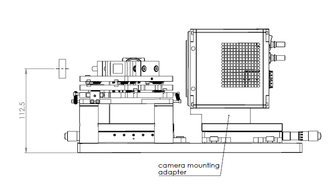 Camera translation stage adapter | Self made (kinetix_to_plate_adapter) | |
2D spectral splitter
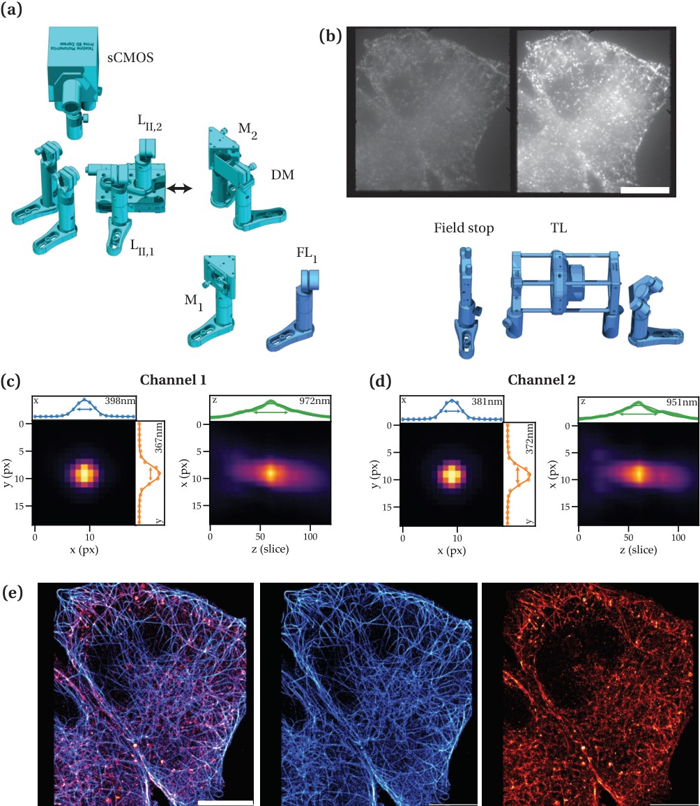
The second detection arm splits the field into up to four spectral channels that are tiled onto a single sCMOS sensor, which makes simultaneous multicolour imaging robust against sample motion and against bleaching between sequential colour frames. The channels are separated by ultraflat dichroics in a mono-to-quad view splitting platform and re-imaged by a common Fourier lens pair; the shared square field stop with four independently positionable edges defines the tile size.
Channel registration and the point spread function of each channel are calibrated on beads. The measured PSF widths of the two main channels agree to within a few percent laterally (about 0.37–0.40 µm) and axially (about 0.95–0.97 µm), which is what allows localisations from different channels to be combined into a single, spectrally demixed reconstruction.
| id | Title | Description | Image | Notes | Costs/Supplier |
|---|---|---|---|---|---|
| 1 | Path separation mirror Mch | Kinematic mirror mount on magnetic base for path separation | The magnetic base allows switching between detection arms without realignment | Mad City Labs/ Thorlabs/ | |
| 2 | MadView multiview beam splitting platform | Mono-to-quad view adaptable beam-splitting system designed for multi-color Single Molecule Microscopy imaging. | Mad City Labs/ | ||
| 3 | Dichroic mirror mounts | 6x mounts (2 per split) for 26x38x3mm ultraflat dichroics (λ/4 Peak-to-Valley flatness) | Flatness is critical to avoid channel-dependent aberrations | Thorlabs/ | |
| 4 | Fourier lenses Fci,R1 | 225mm focal length collimation lenses conjugate to the tube lens mounted in SM1L03 lens mount | Mad City labs / | ||
| 5 | Focussing lens | #49-364-INK 25mm Dia. x 200mm FL, VIS-NIR, Inked, Achromatic Lens (400-1000nm) | Edmund optics/ 120€ | ||
| 6 | sCMOs camera | Teledyne Photometrics BSI Express | 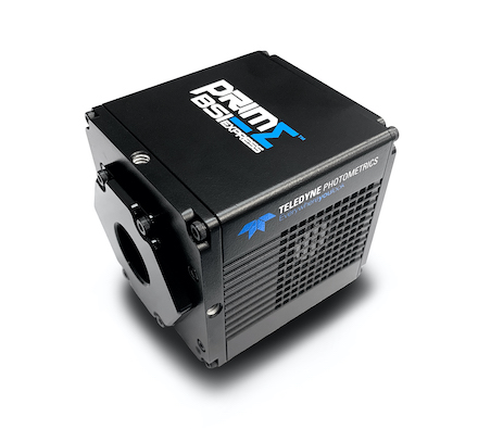 Teledyne Photometrics BSI Express | 2048 x 2048 pixel, air cooled, 43Hz full range full chip, high sensitivity sCMOS | Teledyne Photometrics |
| 7 | Aperture / field stop | SP 60 square aperture with 4 separately positionable edges | Square aperture with 4 separately positionable edges | max. 12 x 12 mm, shared among both detection paths (needs to be manually adjusted to preset FOVs) | Owis/ 450€ |
| 8 | Emission filters | One bandpass filter per spectral channel behind the splitting dichroics | Filter set follows the FPbase configuration | AHF, Semrock | |
| 9 | Folding mirrors M1, M2 | Kinematically mounted broadband dielectric mirrors that fold the split channels onto their tiles on the sensor | Thorlabs | ||
Event-based sensor path
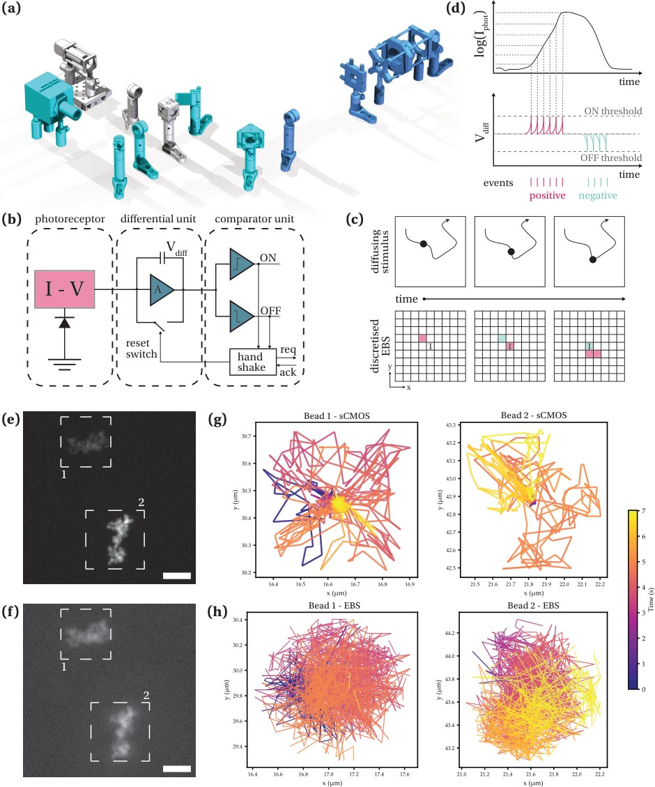
A third detection arm carries an event-based sensor (EBS). Instead of integrating frames, every pixel reports asynchronous ON/OFF events whenever the logarithm of the incident intensity crosses a threshold, which gives microsecond temporal resolution at low data rates for sparse, moving signals. On PRISM the arm shares the splitter path through a 50:50 beamsplitter, so the same field can be recorded on the sCMOS and on the EBS at the same time. That makes the arm useful for fast single-particle tracking, where the frame rate of a conventional camera limits the accessible dynamics.
| id | Title | Description | Image | Notes | Costs/Supplier |
|---|---|---|---|---|---|
| 1 | Event-based sensor | Prophesee EVK4 event camera with a Sony IMX636 sensor, 1280 × 720 pixels at 4.86 µm pitch | Recorded through Metavision in EVT3 format (sensor generation 4.2); bias settings are stored alongside each recording | Prophesee | |
| 2 | Beamsplitter cube | Thorlabs CCM1-BS013/M cage-cube-mounted non-polarising 50:50 beamsplitter, splitting the arm between the sCMOS and the event sensor | Allows the same field to be recorded on both sensors simultaneously for the frame-based versus event-based comparison | Thorlabs | |
| 3 | Relay lens | Focussing lens imaging the relayed intermediate image onto the event sensor | F=160mm achromatic doublet, as the sensor pitch (4.86 µm) differs from the sCMOS, so the effective sampling on the EBS is 113.9nm | Edmund Optics | |
| 4 | Sensor mount | Adapter and post assembly holding the EVK4 at the beam height of the detection breadboard | Prophesee_EV4K mounting hardware via C-mount, cage plate and cage system to ensure orthogonality + a lens tube for light protection | self made | |
Focus lock
Axial drift is suppressed by an infrared reflection focus lock. An 830 nm collimated diode beam is coupled in through the micro-mirror path, totally internally reflected at the sample coverslip and imaged onto a quadrant photodiode; the lateral position of the reflected spot on the quadrants is proportional to the axial displacement of the coverslip and is fed back onto the piezo z-stage. Readout and feedback are handled by the Mad City Labs TIRF Lock, which closes the loop in software onto the nanopositioner. Because the lock operates beyond the emission bands and enters through the micro-mirror path, it can run simultaneously with dichroic-based Epi-TIRF imaging.
The benefit shows in long single-molecule acquisitions: with the lock engaged the mean axial position of the localisations stays flat over tens of thousands of frames, while it drifts continuously when the lock is off — in particular with the incubator running, which is exactly the regime needed for live-cell measurements.
| id | Title | Description | Image | Notes | Costs/Supplier |
|---|---|---|---|---|---|
| 1 | IR diode laser | 830 nm collimated laser diode module, coupled into the micro-mirror TIRF path through the longpass flip mirror | Outside the detection bands, so it does not contaminate the fluorescence channels. The CAD assembly TIRF_lock_excitation carries a Thorlabs CPS-series module as a stand-in geometry | Thorlabs | |
| 2 | Beam steering | KCB1EC/M right-angle kinematic mount and a four-inch two-mirror periscope on ER8 cage rods, with a KAD11F kinematic adapter and an XYT1/M XY translation mount for lateral positioning of the beam in the back focal plane | Positioning in the pupil sets the incidence angle and therefore the lateral shift per unit of defocus | Thorlabs | |
| 3 | Focussing optics | Lens and right angle prism (PS615 and AMA007 mounting adapter) that focus the returning NIR beam via a mirror onto the QPD | Thorlabs, Mad City Labs | ||
| 4 | IR separation dichroic | Thorlabs DMLP730B longpass dichroic (730 nm cut-on) separating the returning IR beam from the fluorescence emission | Mounted in a KM100B/M kinematic mount in the CAD assembly | Thorlabs | |
| 5 | Reflection readout | Quadrant photodiode head of the Mad City Labs TIRF Lock, reading the position of the beam reflected at the coverslip; 400–1000 nm range, 2.4 × 2.4 mm sensor, peak responsivity 0.4 A/W at 635 nm and 0.67 A/W at 900 nm | The lateral spot position on the quadrants encodes the axial sample position | Mad City Labs | |
| 6 | Controller | Mad City Labs TIRF Lock controller, connected over USB 2.0 with a LabVIEW based software interface that closes the loop from the quadrant signal onto the nanopositioner | Software feedback rather than an analogue loop; designed for the RM21 platform together with the MicroMirror TIRF system and TIRF module | Mad City Labs | |
| 7 | Actuator | Mad City Labs NanoDrive piezo z-stage, driven in closed loop from the readout signal | Shared with z-stack acquisition and multiplane calibration | Mad City Labs/ | |
Control and acquisition
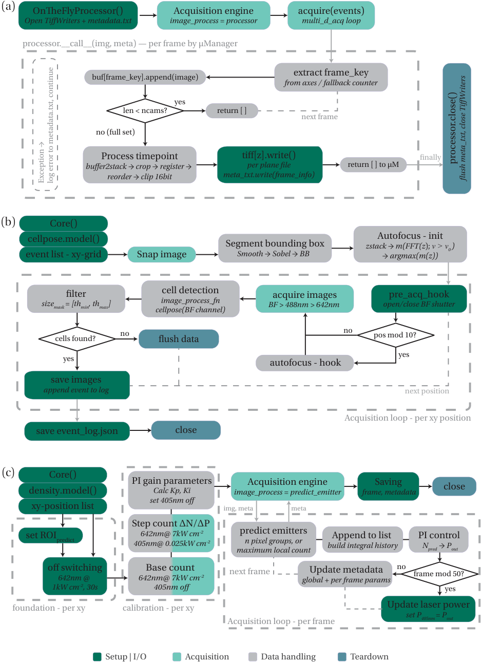
All devices are addressed through micro-manager 2: the two Kinetix cameras through PVCAM as a combined MultiCamera device, the BSI Express on the splitter path, the Mad City Labs MicroDrive XY and Z stages and the NanoDrive piezo, the laser heads over their serial interfaces, and the shutters and line switching through an Arduino hub. Acquisition routines are written against pycro-manager, which allows the acquisition engine to be extended with per-frame image processors and hooks.
Three routines carry most of the day-to-day work: an on-the-fly processor that regroups the interleaved multi-camera stream into per-plane TIFF files with matching metadata while the acquisition is running; an unattended multi-position routine that autofocuses, segments the brightfield channel with Cellpose and only stores fields that actually contain cells; and a closed-loop STORM controller that estimates the density of active emitters per frame and adjusts the 405 nm reactivation power through a PI controller to hold the blinking density in the optimal range.
| id | Device / component | Description | Image | micro-manager device / notes | Costs/Supplier |
|---|---|---|---|---|---|
| 1 | Acquisition software | micro-manager 2 for device control, with beanshell scripts for the camera ROIs of the different splitter geometries and pycro-manager for scripted acquisitions | ROI scripts exist per configuration (2×2 splitter, 3×2 and 4×2 Scoptonic splitter, multicolour splitter) | open source | |
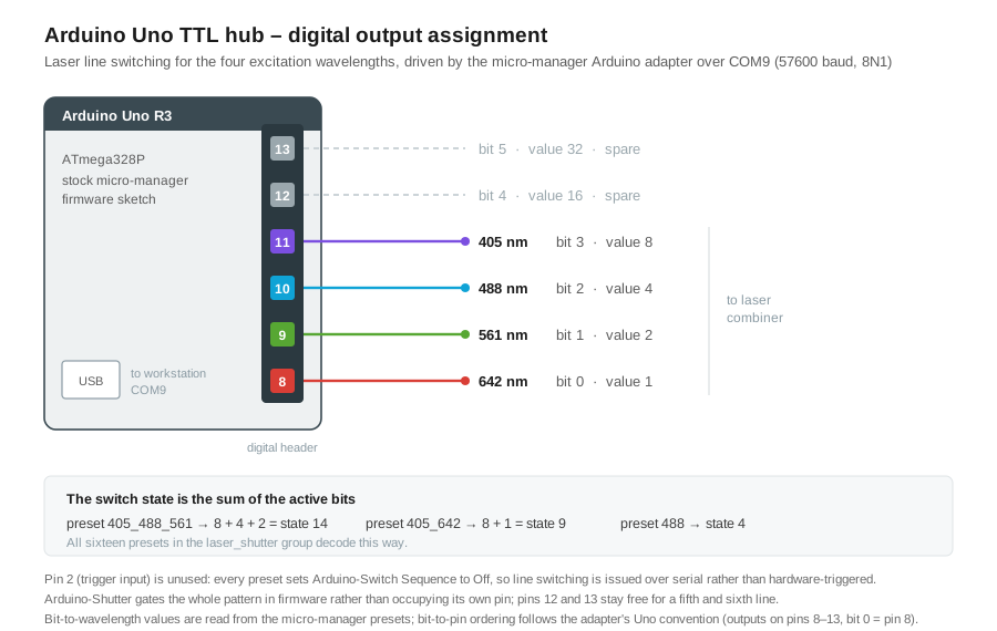
| 2 | TTL hub | Arduino Uno running the stock micro-manager Arduino firmware, driving the laser line switching and the shutters over a serial port | Arduino-Hub with the Arduino-Switch and Arduino-Shutter child devices; COM9 at 57600 baud, 8N1, no handshaking, normal logic. The switch state is a bitmask over the digital outputs on pins 8–13, of which four are used (see the diagram above): 642 nm on pin 8 (value 1), 561 nm on pin 9 (value 2), 488 nm on pin 10 (value 4) and 405 nm on pin 11 (value 8), so a combined state such as 405 + 488 + 561 is written as 14. The micro-manager sketch targets the ATmega328P, so an Uno R3 rather than an R4 is the safe board for a rebuild | Arduino / ~25€ | |
| 3 | Cameras | Two Kinetix and one BSI Express addressed through the PVCAM adapter; the two Kinetix are combined into one logical device for synchronous multiplane acquisition | Camera-1, Camera-2 (PVCAM) and MultiCamera (Utilities) | Teledyne Photometrics | |
| 4 | Stages | Mad City Labs MicroDrive xy and z stages for coarse positioning and the NanoDrive piezo for fine z | MicroDrive XY Stage, MicroDrive Z Stage (MCL_MicroDrive) and MCL NanoDrive Z Stage (MCL_NanoDrive) | Mad City Labs | |
| 5 | Laser control | Serial control of the four excitation lines, with dedicated adapters for the 561 nm and 405 nm heads and generic serial devices for the 488 nm and 642 nm heads | 561 - LaserQuantum (LaserQuantumLaser), 405 - iBeamSmartCW (Toptica_iBeamSmartCW), 488 - Sapphire and 642 - MBPC (UserDefinedSerial); config groups laser_I/O and laser_shutter | — | |
| 6 | Event camera acquisition | Prophesee Metavision software recording EVT3 raw streams with per-recording bias settings, run alongside the micro-manager acquisition | Not integrated into the micro-manager acquisition engine. Synchronisation with the sCMOS stream from the data itself, using the shutter opening as reference. | Prophesee | |
| 7 | Environmental control logging | Python service (tctrl) that logs and plots the Okolab temperature and CO2 readings over the measurement | Produces the traces shown in the incubator figure | self made | |
| 8 | On-line analysis | Cellpose segmentation of the brightfield channel for unattended acquisition, and an emitter density estimator feeding the PI controller for the 405 nm reactivation power | Run as pycro-manager image processors; model weights and thresholds are stored with the acquisition metadata | open source | |
| 9 | Acquisition computer | Supermicro Super Server on an H12SSL-NT mainboard with an AMD EPYC 7502 32-core processor at 2.5 GHz (64 logical processors) and 128 GB RAM, running 64-bit Windows 10 Enterprise (build 19045) | The core count and memory carry the two full-chip Kinetix streams plus the on-the-fly per-plane writing and on-line segmentation | Supermicro | |
Characterisation and performance
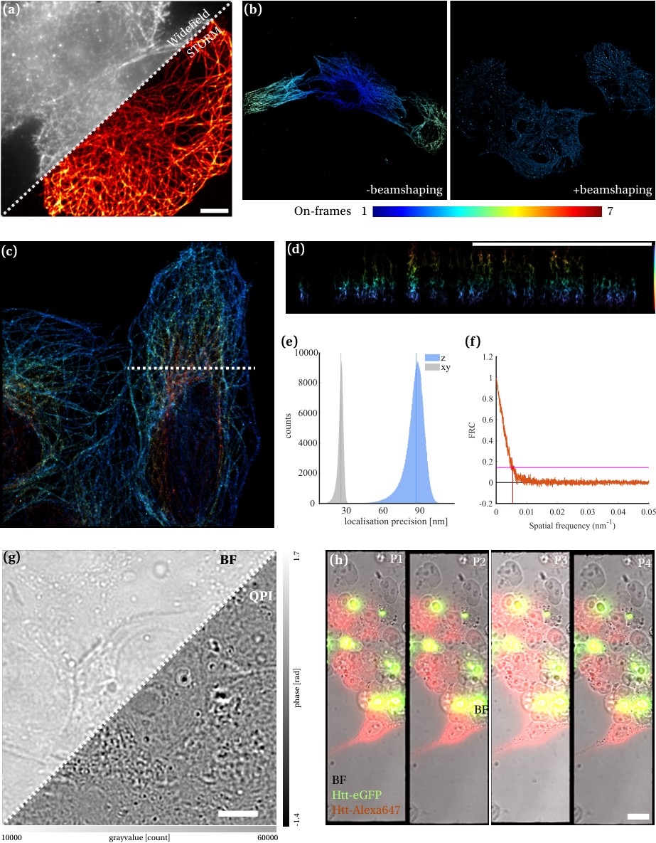
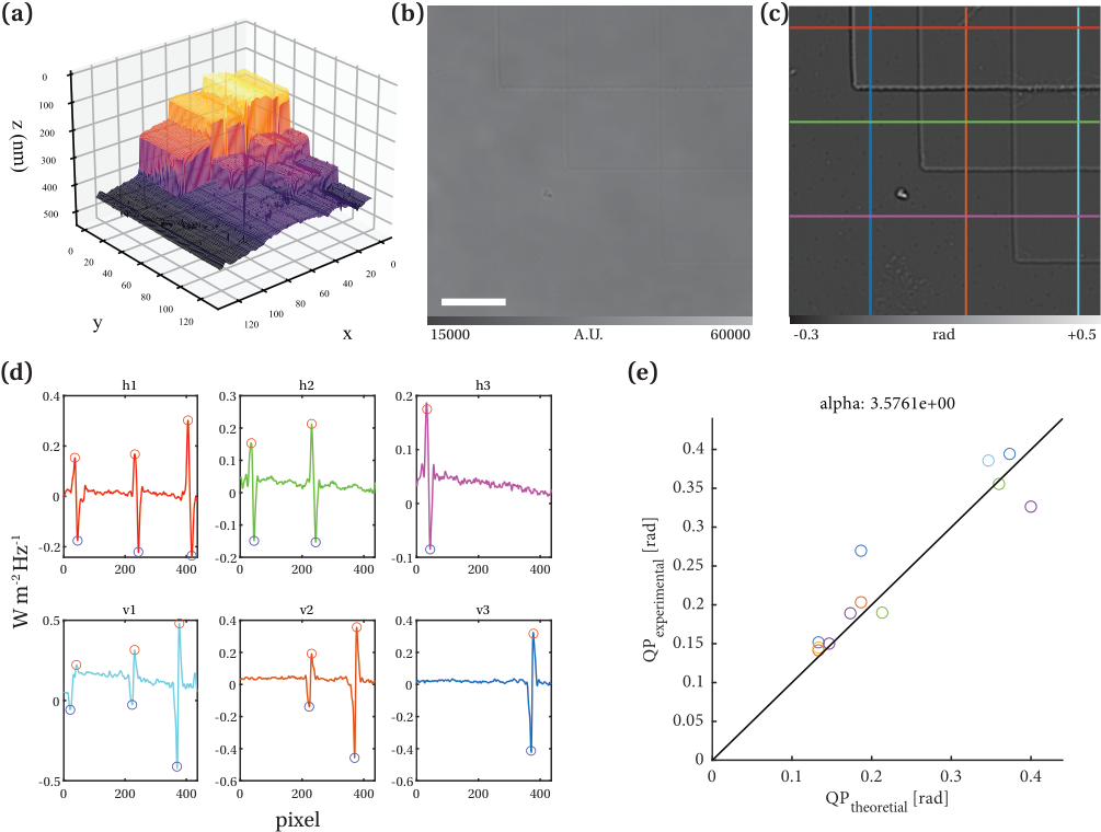
The instrument is characterised with a small set of routine measurements: pixel size against a calibration ruler, illumination flatness per line, plane positions from bead stacks, PSF per spectral channel, mechanical and axial stability, and a phase calibration against a step of known height for the quantitative phase modality. The standards and routines used for each are listed below.
| id | Measurement | Standard / sample | Image | Routine | Result |
|---|---|---|---|---|---|
| 1 | Pixel size | Calibration ruler with 10 µm line spacing, R1L3S2P | Column or row projection with automatic bright-peak / dark-valley selection, outlier rejection on the inter-line distances; on the BSI the two differently illuminated sensor halves are evaluated separately as a uniformity cross-check | 108 nm per pixel on both the BSI Express and the Kinetix | |
| 2 | Beam homogeneity | Direct imaging of the beam on the monitoring camera, per laser line, before and after the beam shaper | FWHM, plateau uniformity and flatness factor from the recorded profiles | See the illumination figure; flat-top profiles for all four lines | |
| 3 | Collimation | Thorlabs shearing interferometer, size matched to the 6 mm (1/e2) collimated beams | Checked per line after the beam expander; a wedged shear plate turns residual divergence into a tilt of the interference fringes against the reference line | Collimation verified for each expander | |
| 4 | Plane positions and PSF | Fluorescent bead sample made from 100nm TetraSpeck beads T14792 | Piezo z-stack over the beads, median bead brightness per sub-image versus z-slice, maxima give plane positions and inter-plane distances | Eight planes calibrated per acquisition configuration | |
| 5 | Channel PSF | Same bead sample, imaged through the spectral splitter | Lateral and axial profiles fitted per channel | ~0.37–0.40 µm lateral, ~0.95–0.97 µm axial for both channels | |
| 6 | Mechanical stability | Immobilised sample imaged over 104 frames with the environmental control on and off | Lateral position per frame plus the amplitude spectrum of the trace | No dominant vibrational resonance introduced by the incubator; added low-frequency drift | |
| 7 | Axial stability | Single-molecule acquisition with the focus lock engaged and disengaged | Mean axial position of the localisations per frame, drift corrected against the lock-on trace | Flat axial position with the lock on over tens of thousands of frames | |
| 8 | Quantitative phase | Custom etched borosilicate staircase sample, with corners as displayed in panel (a), step height rangning from 50nm to 200nm. | Horizontal and vertical line profiles across the step edges, measured against the theoretical phase to fix the scaling factor | Scaling factor α ≈ 3.58 for the current configuration | |
| 9 | Resolution | Immunolabelled microtubules (tubulin / Alexa 647) in U2OS cells | Localisation precision histograms (NeNA) and Fourier ring correlation on the reconstruction | ~30 nm lateral and ~90 nm axial localisation precision | |
Design files and related pages
- Prism fabrication — assembly of multiplane splitters from off-the-shelf beamsplitters.
- Live-cell incubator — the cage incubator design for the RM21 platform.
- Incubator STEP file — enclosure geometry as used on this system.
- FPbase configuration — spectra of the current filter and splitter configuration.
- GrussmayerLab on GitHub — acquisition and processing code for the multiplane pipeline.