Live Cell Incubator
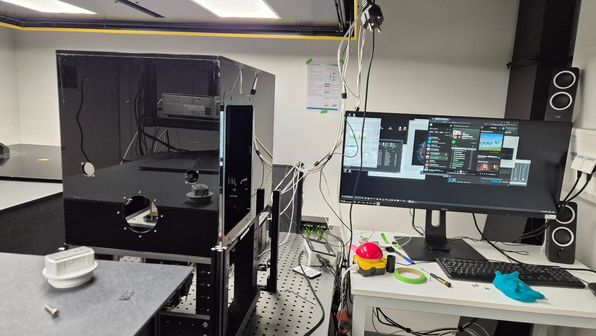
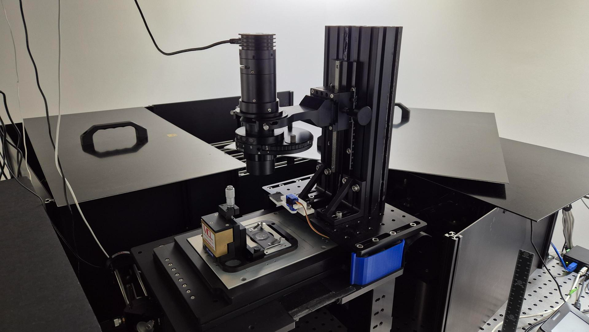
In the current setup there already is an incubator used. In the current incubator there are many openings for gas to escape and the material is wearing down (bending). The main aim for the new incubator is making it airtight as much as possible. The materials used should withstand 37°C and CO² gas.
The connectors of the old incubator will be used in the new incubator and the dimensions will be taken as a guide to draw up the new version. The old incubator is made of loose panels that will be bolted together. The old incubator is placed loosely on the platform. There are big openings to allow cables passing through.
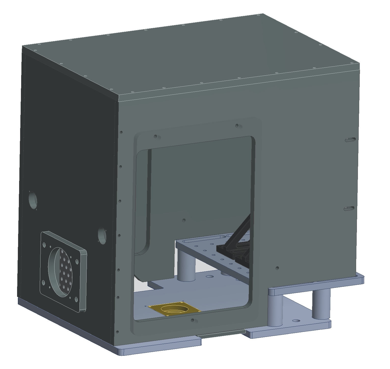
Design
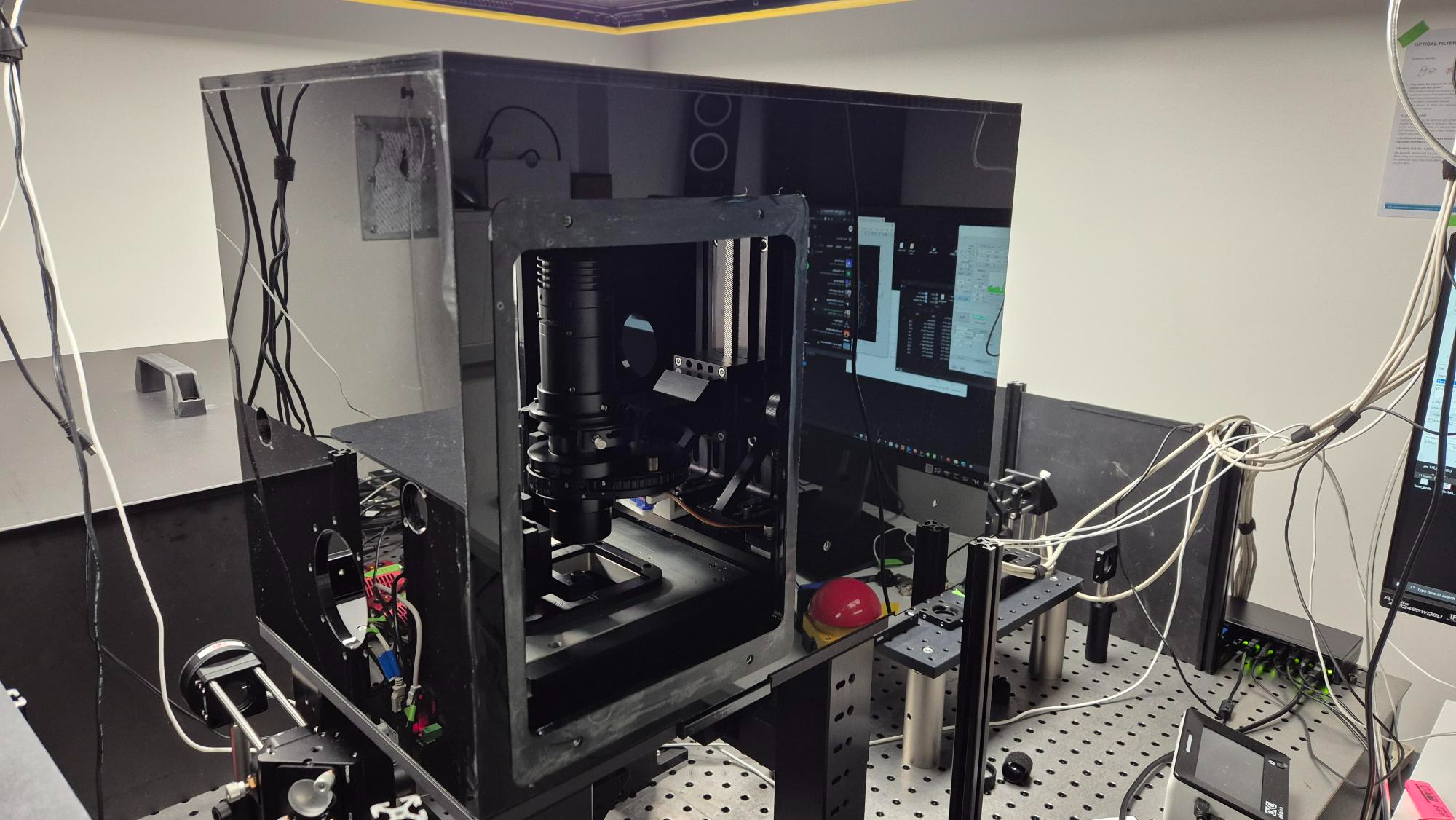
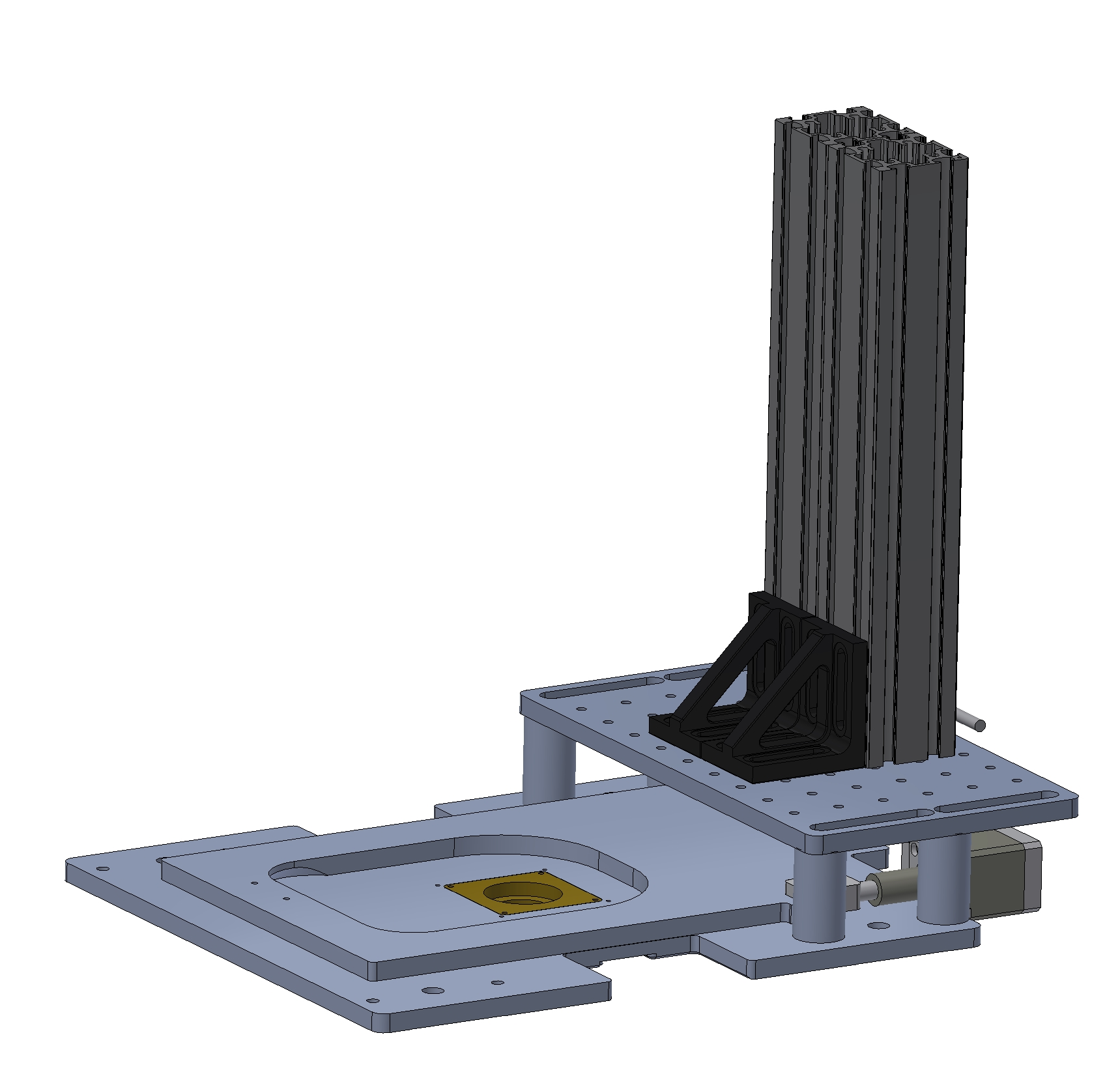
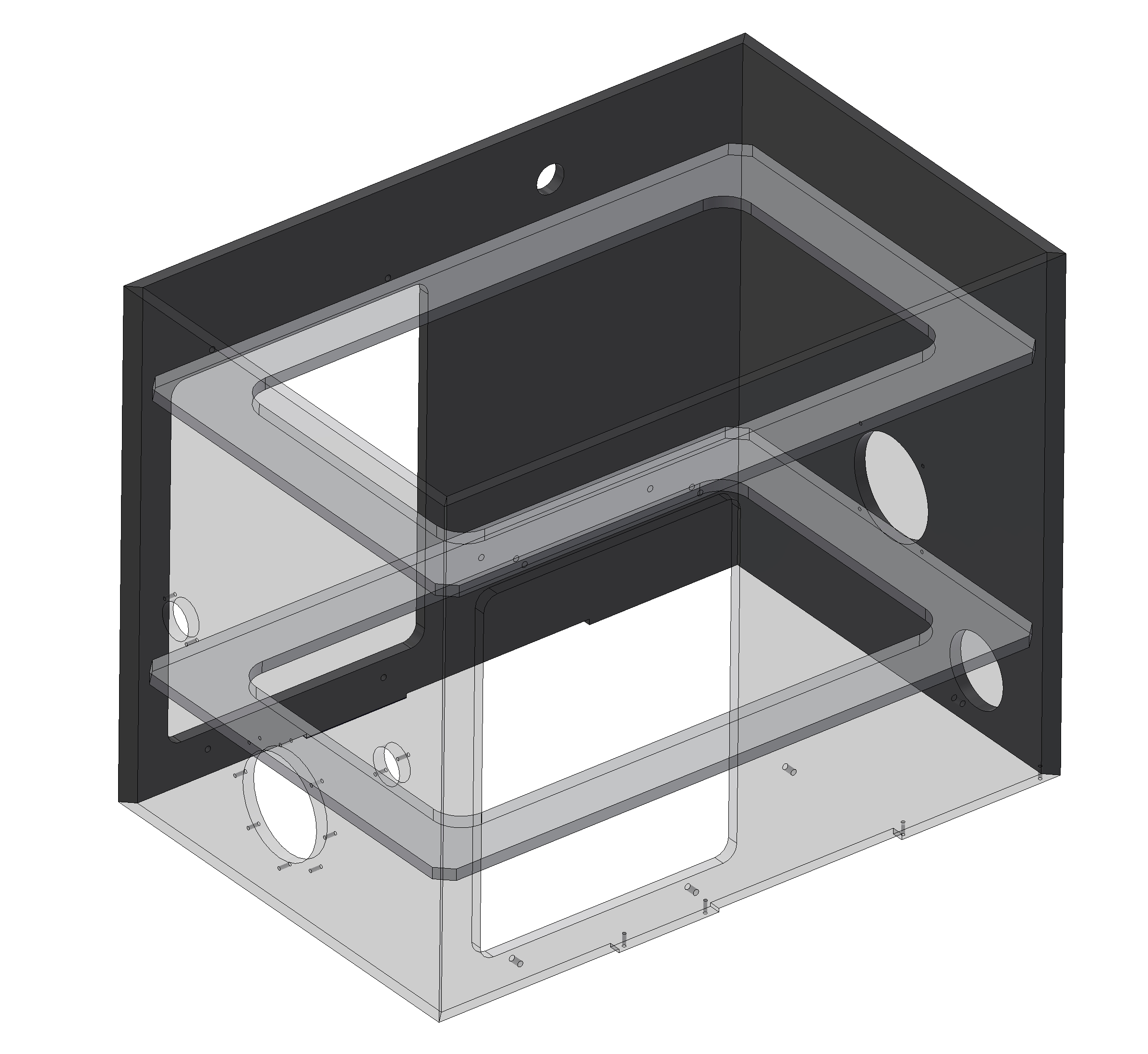
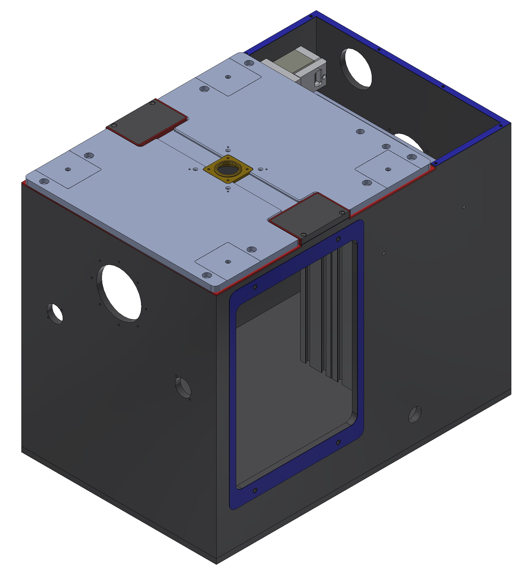
The incubator has to fit on a platform that has two levels. On the top level a column is mounted which has the microscope attached to it. The old incubator sat on top of both levels of the platform, which left gaps between the top and bottom level. The new incubator will sit only on the bottom level en go over the second level completely.
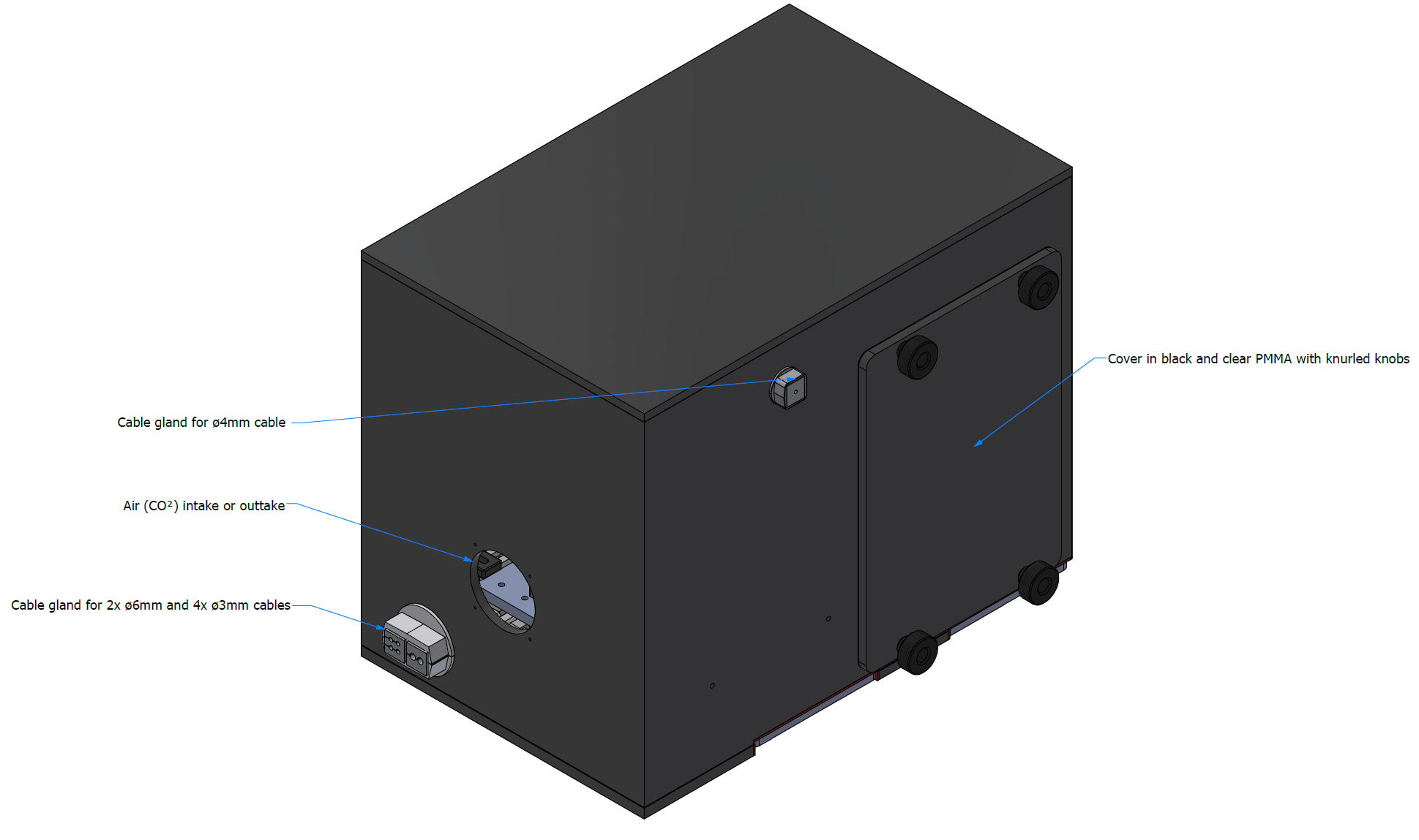
The new incubator will also consist of loose panels but now glued together as much as possible. The edge of the incubator will be covered with a neoprene foam strip to create a seal between the incubator and the platform. The cables will go through a cable gland. The panels of the incubator are made of black non-translucent PMMA (acrylic). The black PMMA does not let light through.
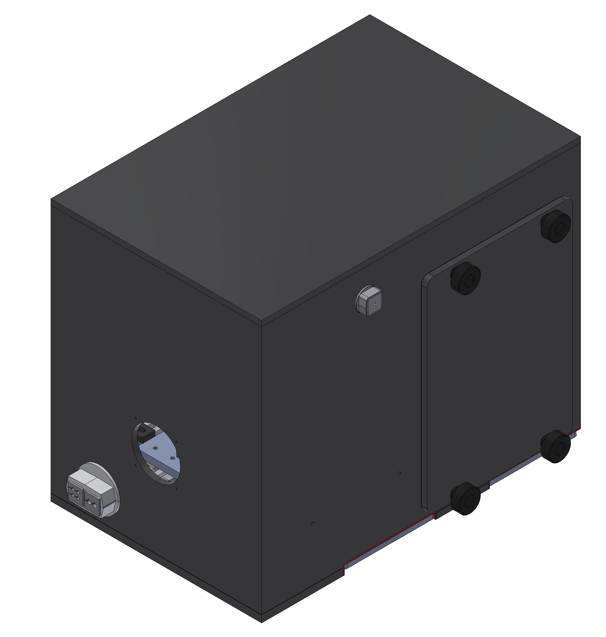
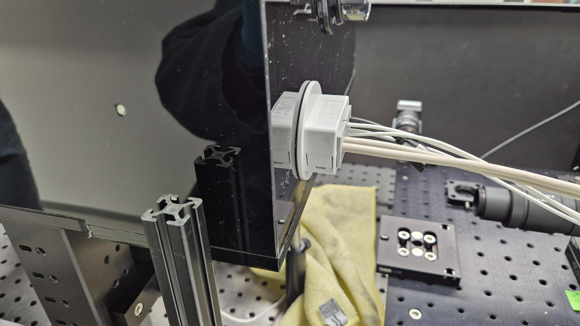
There are two ø6mm cables and four ø3mm cables coming from the right side and one ø4mm cable on the back. To let out the cables as airtight as possible the cable glands from the brand Icotek where used. These cable gland can be used without removing the connector.
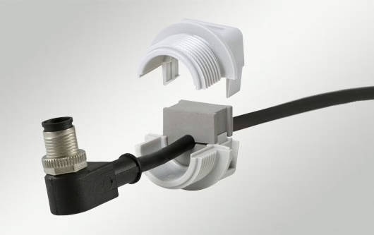
- Due to availability the IP54 versions where used, a better air-tightness is to be expected with the IP68 version.
- During the installation there was an second cable that had to go out at the back. This cable is squeezed with the ø4mm cable in the cable gland.
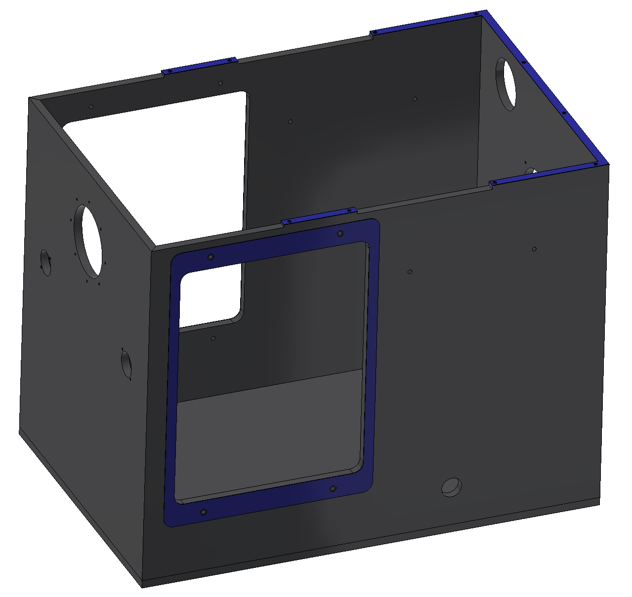
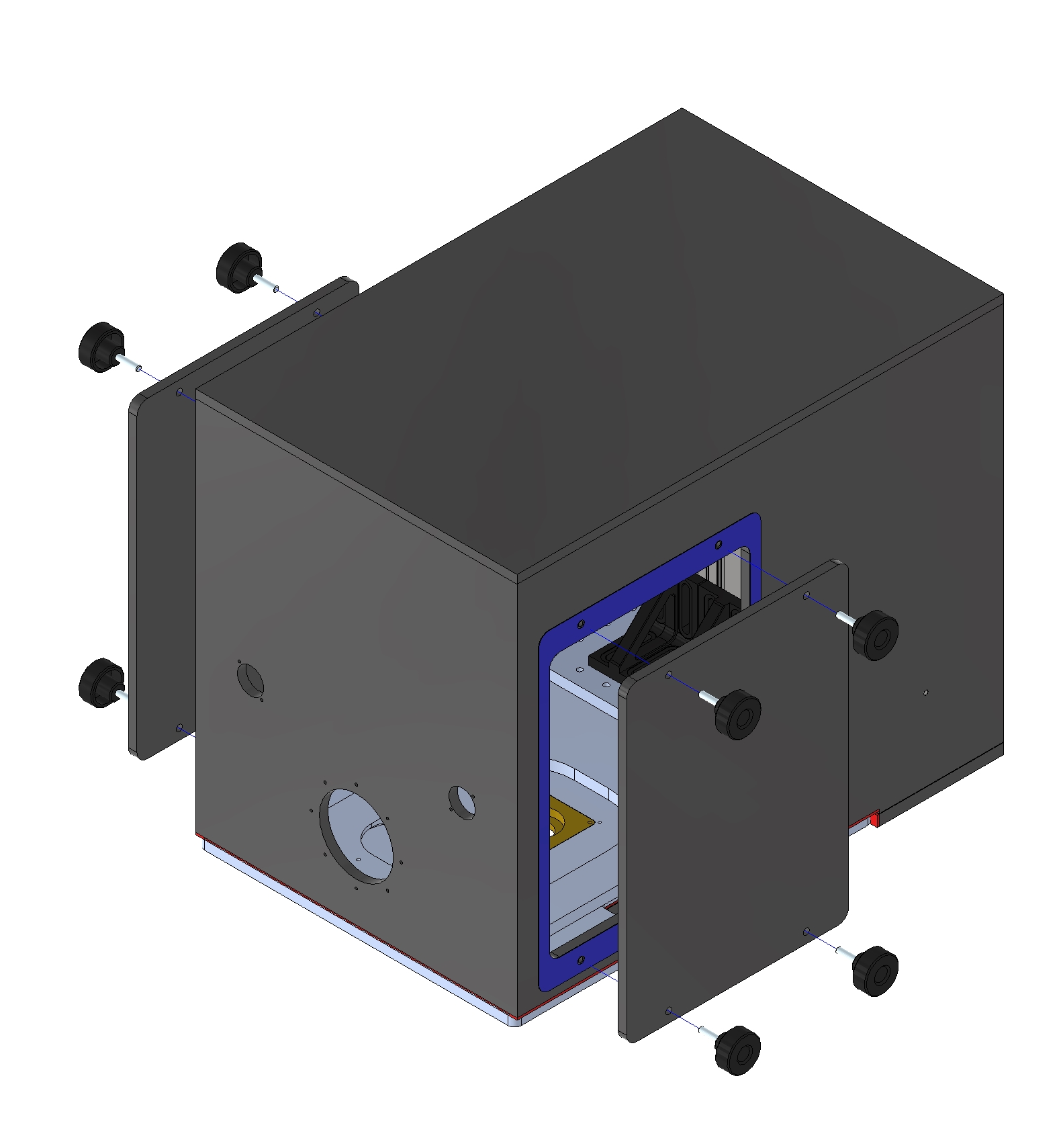
The four side panels and the top panel are glued together with ANGLOSOL CEMENT 700 (two part acrylic adhesive) together. This will create a strong airtight bond. Between the side covers and the incubator is a rubber gasket (the gasket is glued to the incubator).
After placing the incubator on the platform the tree bottom panels can be mounted and then bolted down with M3 bolts. Between the connecting surfaces of the panels and the incubators is a rubber gasket (the gasket is glued to the incubator). All edges of the incubator that make contact with the platform are covered with a foam rubber strip.
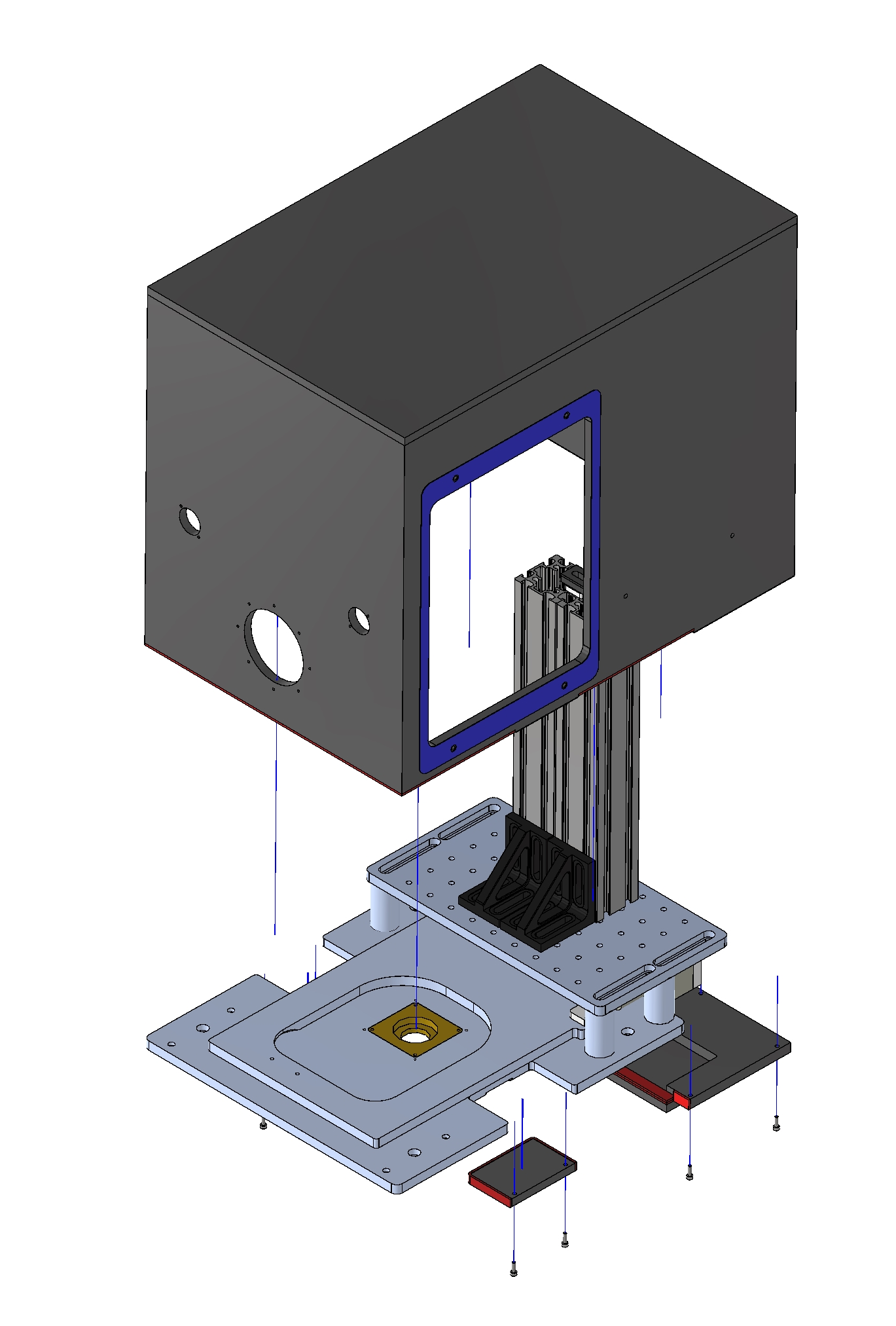
The incubator is secured to the second level of the platform by angle brackets. An extra strip is added to created a adjustable mounting position to fit alignment issues.
Parts To Order
The cable glands and knurled knobs can be orders at RS-Components, the rubber gasket and rubber foam can be ordered at ERIKS, the bracket can be ordered at ITEM, bolts at FABORY and the 8mm black PMMA can be ordered at Vink-Kunststoffen.
| Part | Quantity | Part number | Product Link |
|---|---|---|---|
| RS-COMPONENTS | |||
| Icotek Grey Elastomer Cable Grommet KT 2/6 | 1 | 283-7600 | Link |
| Icotek Grey Elastomer 888mm Cable Grommet KT 4/3 | 1 | 284-4652 | Link |
| Icotek Polycarbonate Cable Trunking Frame, 66 x 66 x 37mm, KVT | 1 | 284-4658 | Link |
| Icotek QVT Series Grey Polycarbonate Cable Gland, M20 Thread, IP54 | 1 | 283-6507 | Link |
| Icotek Grey Elastomer Cable Grommet QT 3 | 1 | 283-6500 | Link |
| Knurled Torque Knob M5 x 20,22mm dia | 10 | 702-7541 | Link |
| ITEM | |||
| Winkel 60x40x20 Zn, schwarz | 4 | 47461 | Link |
| ERIKS | |||
| Prof.CR FEST cel-zelfkl zwart 10x2 L=20 | 20 | Link | |
| Plaat SUPERBA 1400x0,5 | 1 | 10017236 | Link |
| Vink-Kunststoffen | |||
| Altuglas PMMA Plaat Gegoten Zwart 101 48000 3050x2030x8mm | 107859 | Link | |
| FABORY | |||
| Hexagon socket head cap screw DIN 912 Stainless steel A2 M3X10 | 10 | 51.050.030.010 | Link |
| Hexagon socket head cap screw DIN 912 Stainless steel A2 M5X16 | 4 | 51.050.050.016 | Link |
| Hexagon socket head cap screw DIN 912 Stainless steel A2 M6X12 | 8 | 51.050.060.012 | Link |
Manufacturing
All the PMMA plates are laser cut on the TROTEC Speedy 400. 2D outlines of the parts are exported as DXF files. The laser cutter cuts on the line of the dxf. This means that there is no offset compensation in the software. Dimensions of the dxf are adjusted to accommodate for the offset.
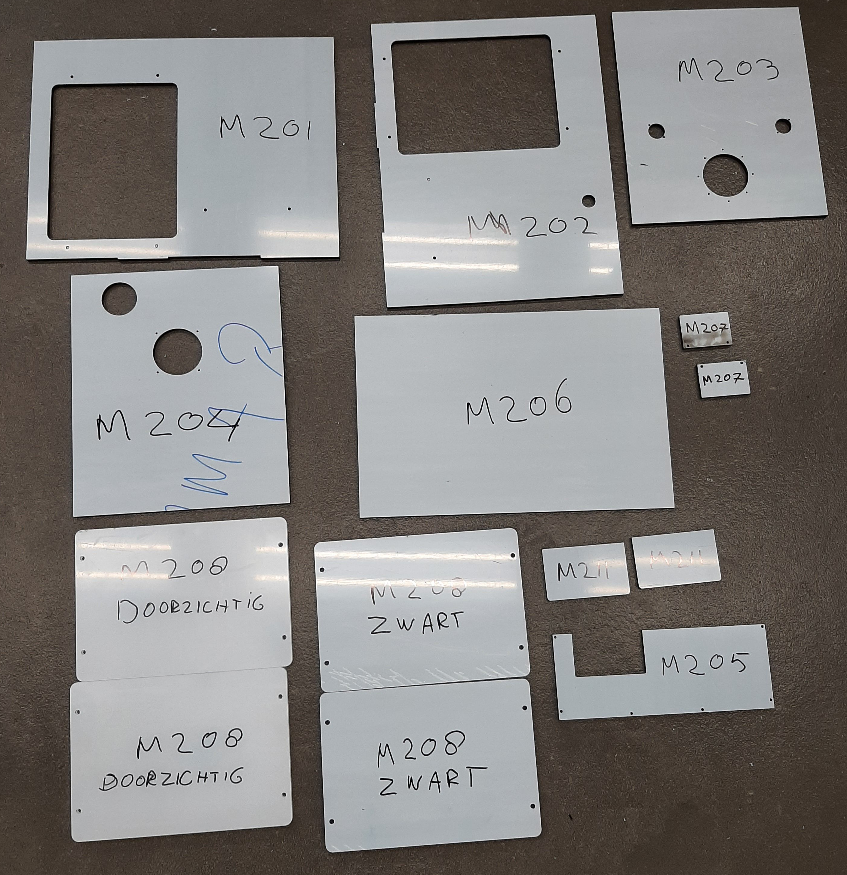
Before gluing the panels the M3 and M5 helicoil thread inserts are placed. The thread holes were kept smaller when cut. The holes for the threads are drilled to the correct size (M3=ø3,1, M5=ø5,2) using the smaller cut holes to position. Then the threads are tapped with the helicoil tap M3 and M5 and the helicoil are inserted. Parts M205 and M211 need to be countersunk for cylindrical M3 bolt heads.
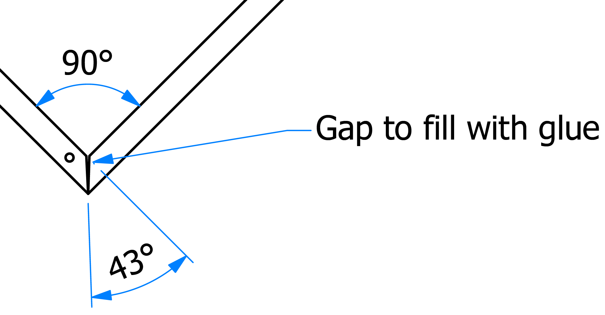
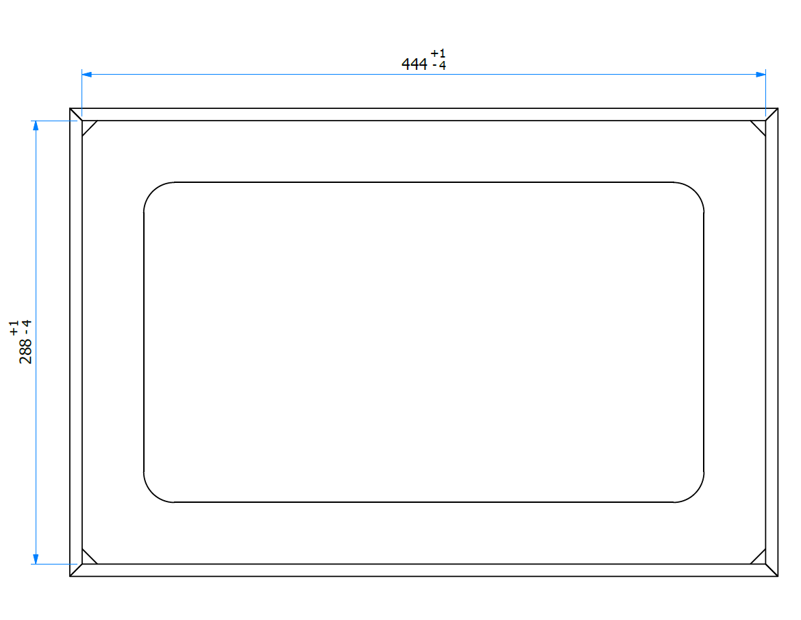
The sides of parts M201 till M204 needs to have a +- 43 degree angle. Two 45° edges will make a 90° corner. With gluing the missing 2°/4° will be filled. The angles are cut on a table saw with the blade angled.

To ensure a proper alignment with gluing two gluing molds are used. These are two plates that have the dimensions of the inside of the box.
- The gluing molds should determine the dimensions of the incubator when gluing. Measure the gluing molds outer dimension to be sure that the dimensions are correct.
Two corresponding adjacent panels are placed next to each other and taped together on the long side. When taped the two panels can be placed in a 90° angle. This is also done with the other two panels. These two sets of panels can be placed together and checked with the gluing mold.
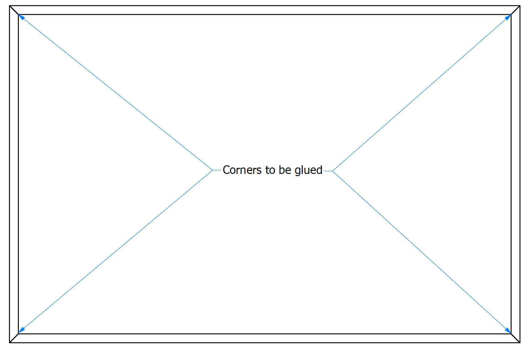
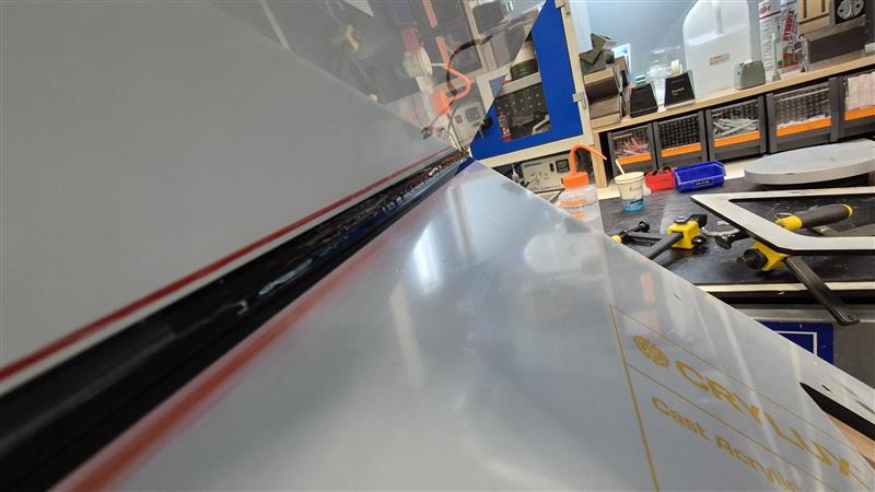
The panels will be glued in an 90° angle block, corner by corner. The side of the corners are taped off so the glue doesn’t run out between the plates, also on the ends of the plate. The corner of the first set of panels is then filled with glue and let to dry. This is repeated for the second set of panels. 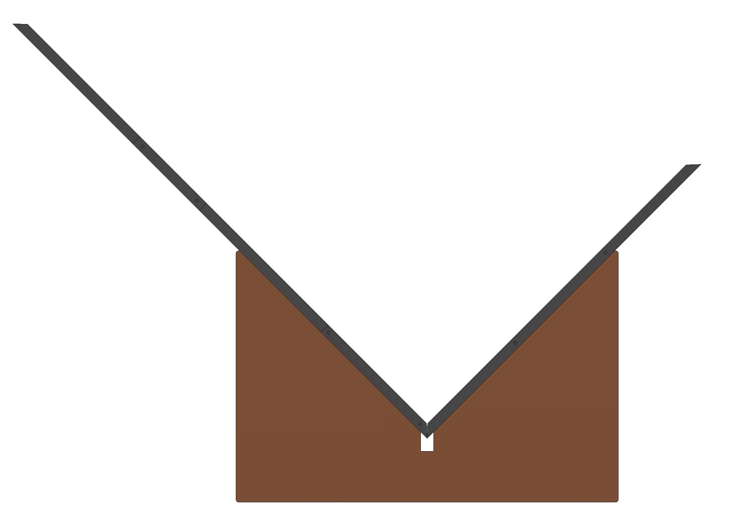
In the angle block together with the gluing mold the remaining corners can be glued. 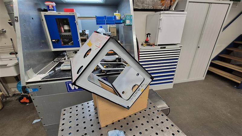
After gluing any overflowing glue needs to be removed. 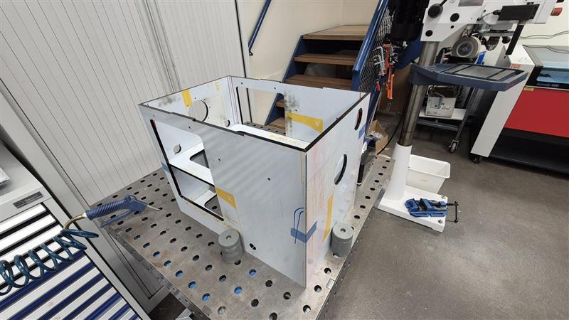
After gluing all the side panels the top panel can be glued. An even layer of glue is put on the top edge of the panels and the top panel is placed on top it. When all panels are glued together the holes on the bottom of the incubator are drilled (ø3,1mm) for M3 Helicoil thread inserts using two drill guides. The drill guides are aligned and clamped to the bottom of the incubator and the holes are drilled through the guides. Then the thread inserts are placed. 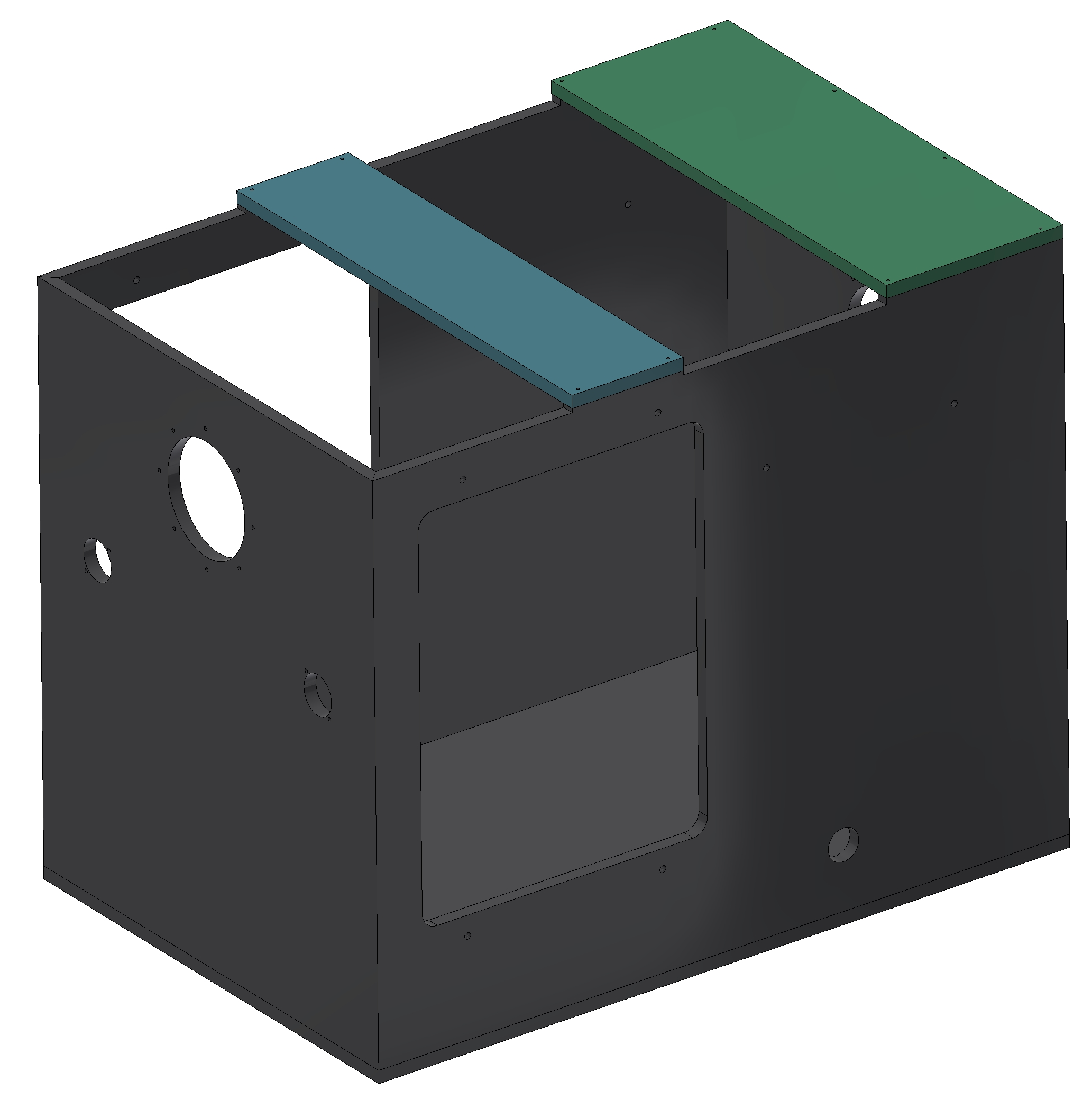
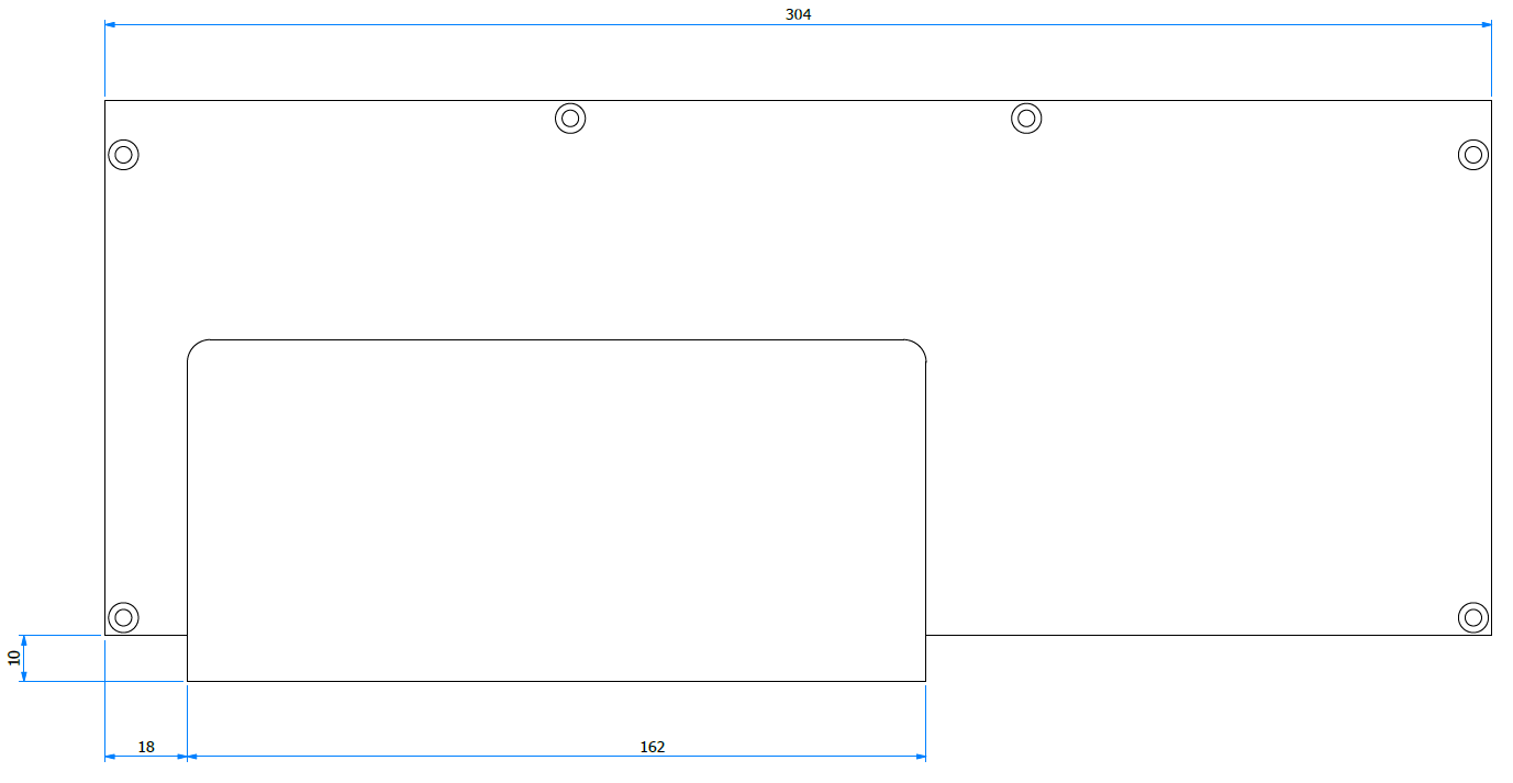
The right bottom panel consists of two plates that need to be glued together. 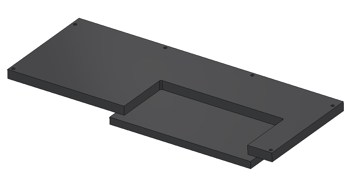
 ![]
![]
- Afterwards part M205 is made of 10mm thick plate instead of 8mm like the rest of the panels for extra clearance when installing.
The rubber gaskets between the bolted parts are cut out of a NBR rubber plate using a water-jet cutting machine (cut with only water, no abrasive). The gaskets are glued to the incubator using Cyanolit.
- Instead of gluing the gasket, a gasket with on one side sticky tape can be used. Due to availability the standard sheet is used.
Then the 2mm foam rubber is put on the bottom edges of the incubator. The foam rubber is sticky on one side. The foam rubber is put on the edge and cut to length with a sharp knife. 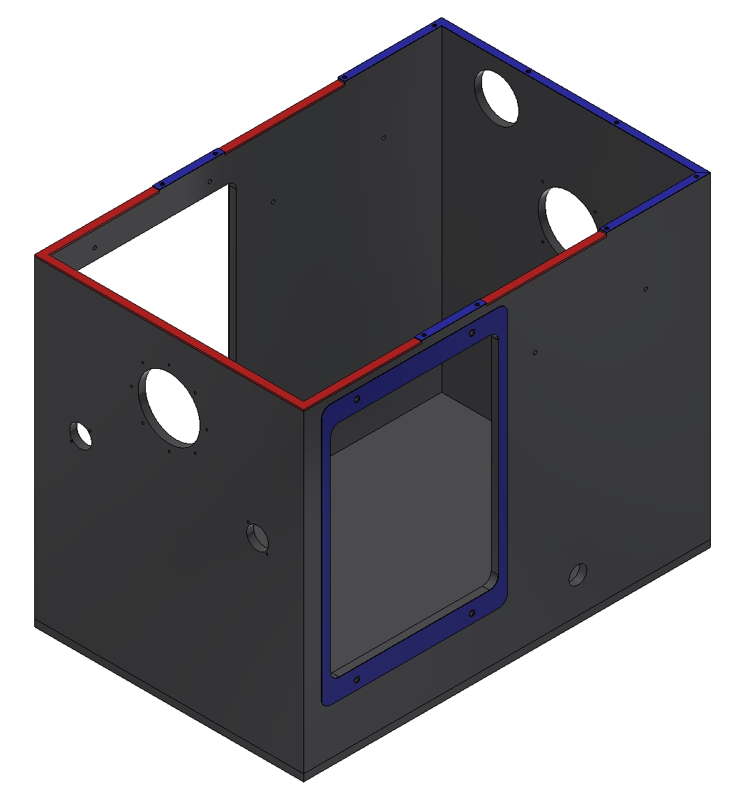
The foam rubber is also placed on the bottom covers. To accommodate for the 10mm plate two strips of 2mm foam are placed on top of each other on the flat panel. 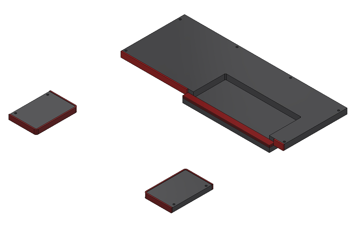
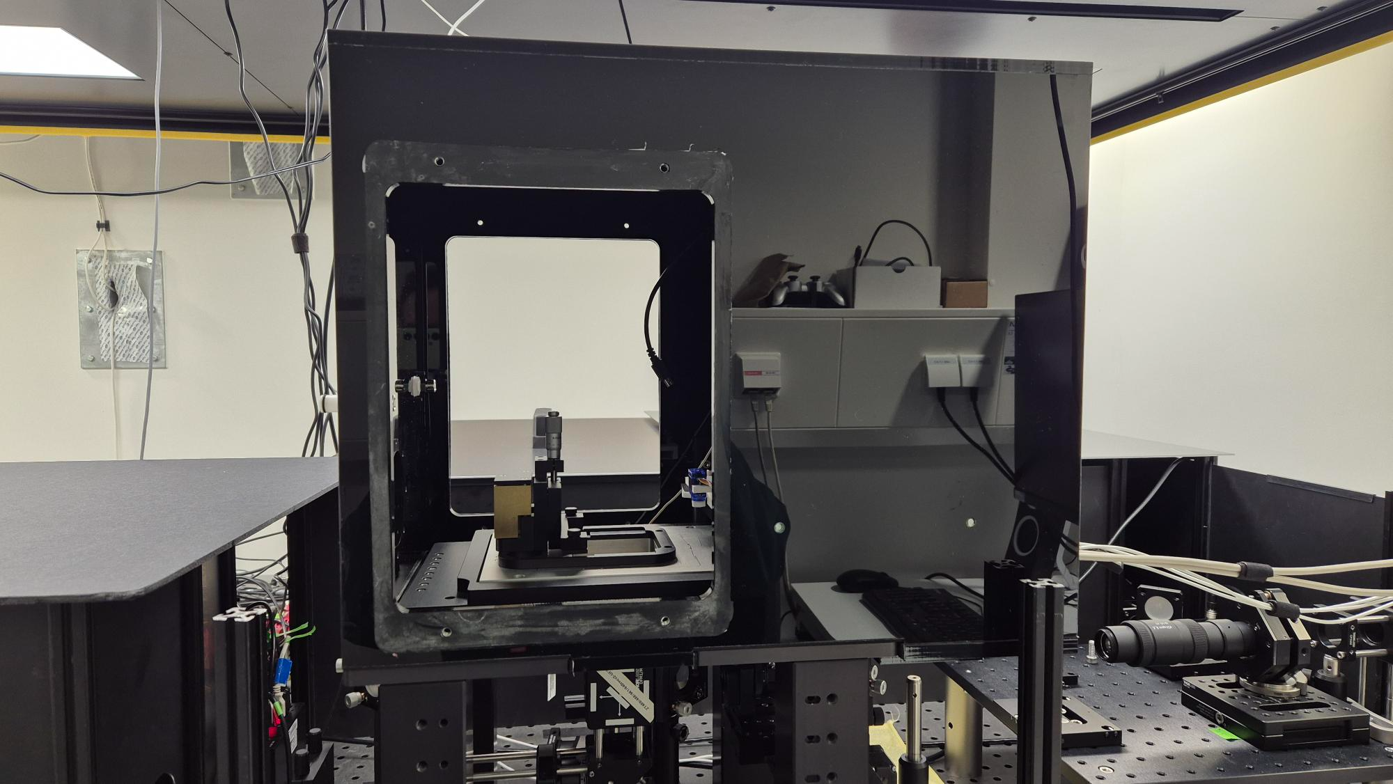
Assembly
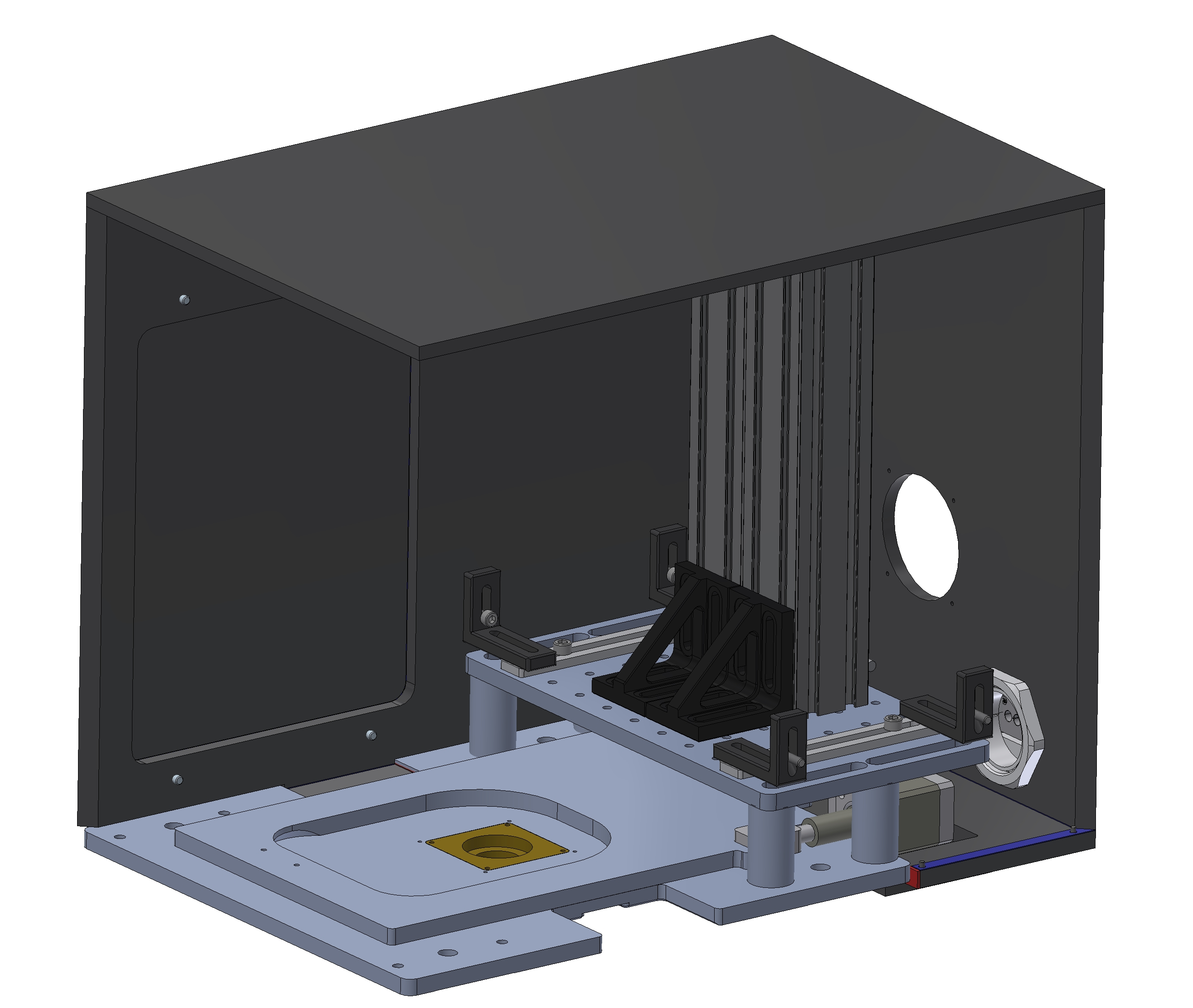
First the angle brackets and adjuster plate are mounted to the inside of the incubator. The bolts aren’t tightened completely so it can be move in position when placed on the platform. 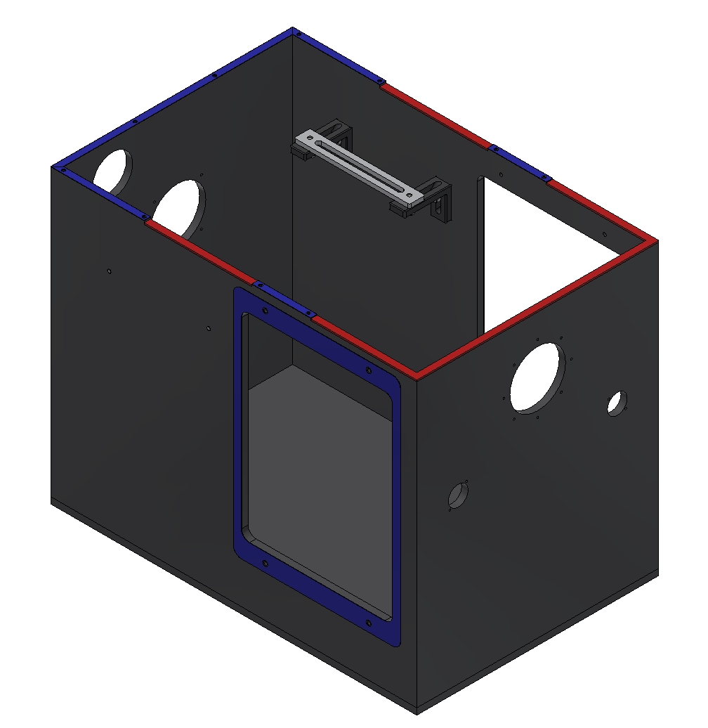
Carefully the incubator is placed over the column and microscope onto the platform. Then the bottom covers M211 are fitted en bolted down. 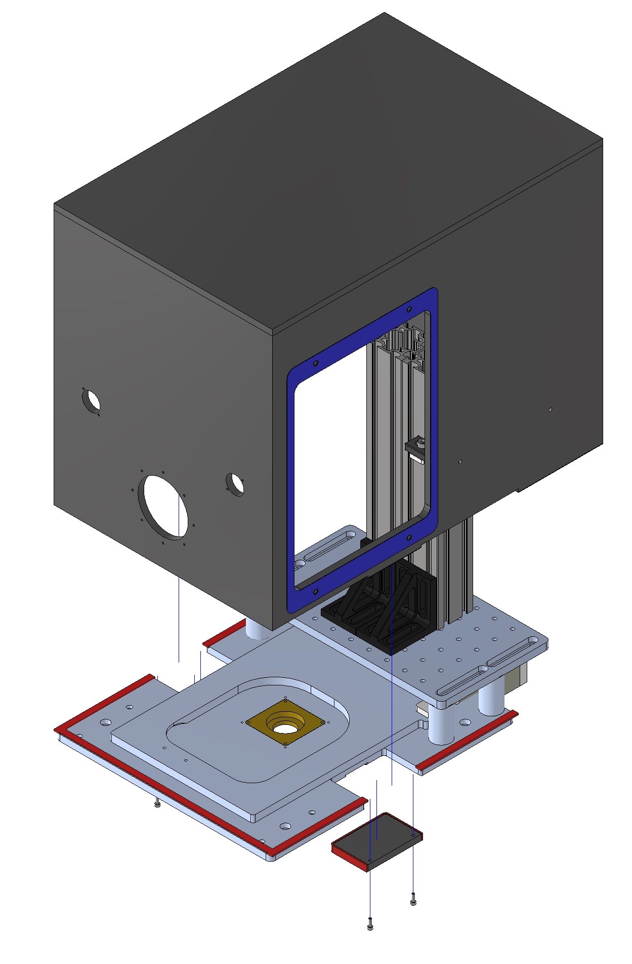
 After the bottom covers are mounted the two adjuster plates can be bolted to the platform. The bolts of the brackets can now be tightened.
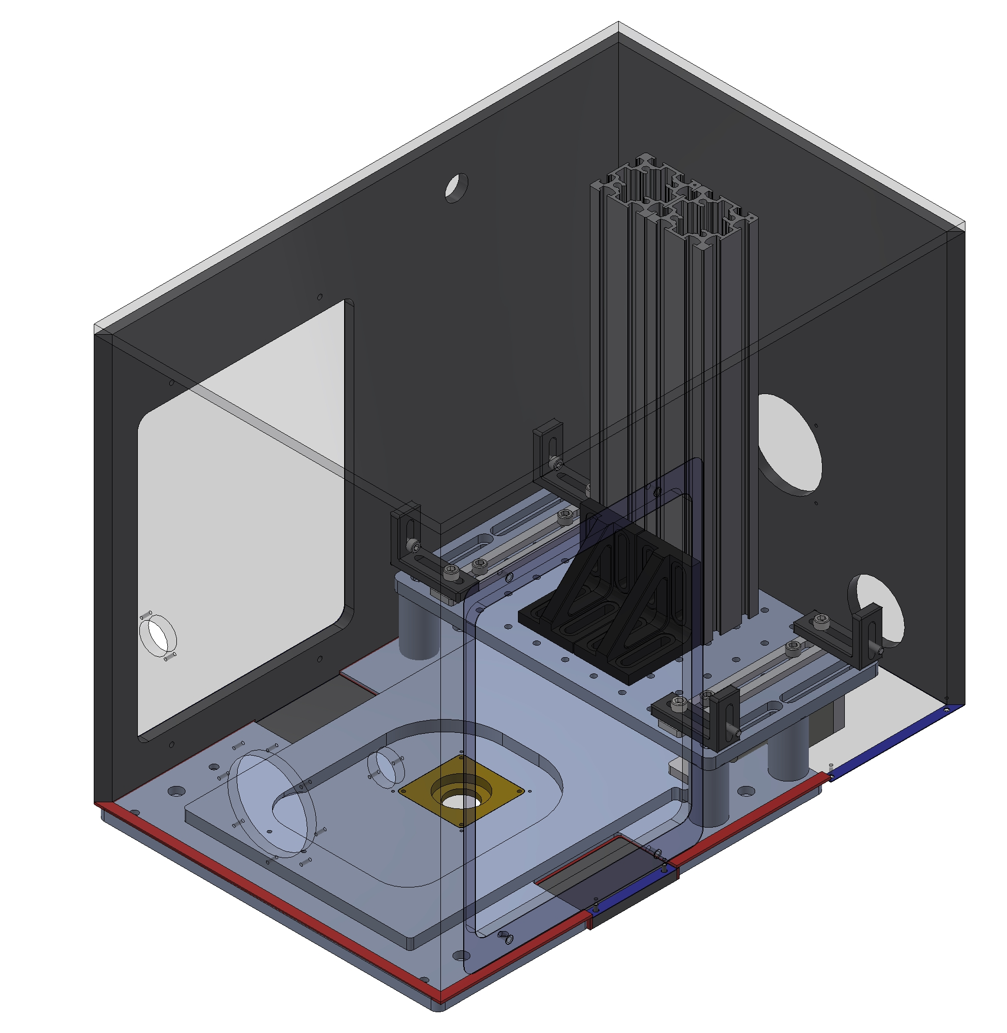
 The last bottom cover can be mounted.
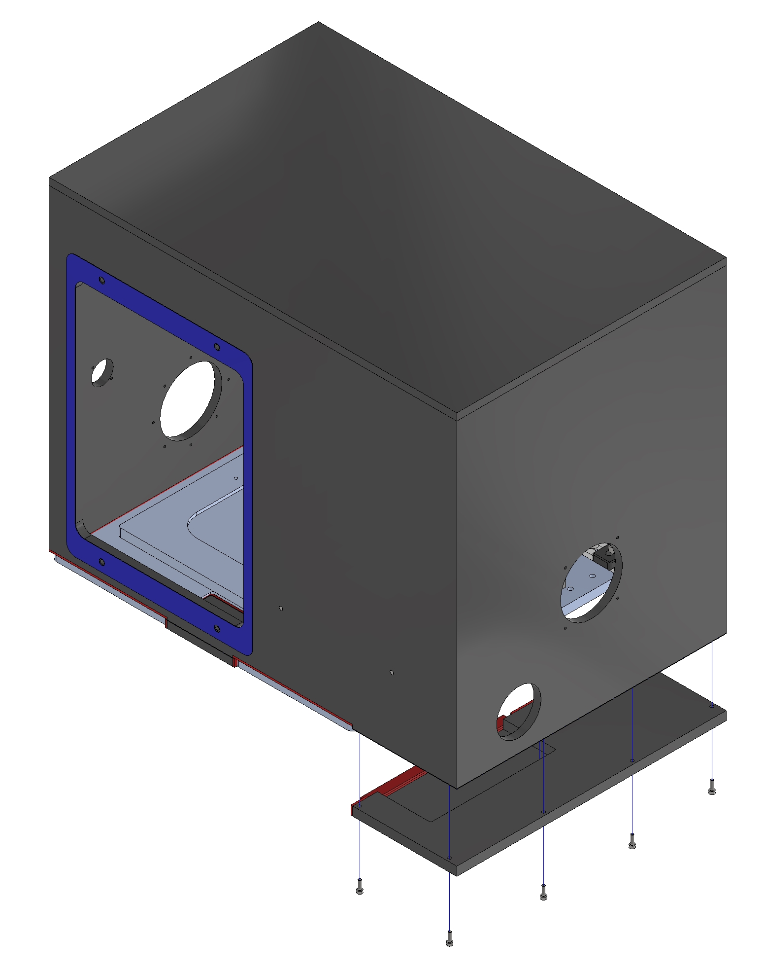
The cables can be fitted through the cable glands and the cable glands can be place inside the incubator. 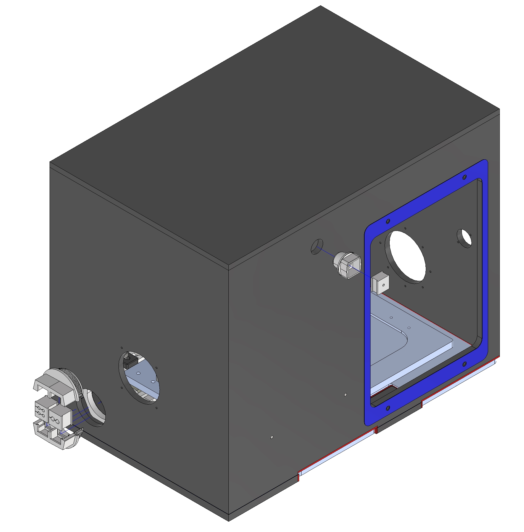
 The rest of the (air) connectors can be mounted to the incubator and the side covers can be placed.
Implementation